
Page 381 - Phase Space Optics Fundamentals and Applications
P. 381
362 Chapter Eleven
the last filter before a square-law detector to be a phase-only filter. The
final filter must be an amplitude-only filter, but it may be either time-
stationary or time-nonstationary. If it is the former, then the first filter
must be a time-nonstationary filter, but it can be either an amplitude
or a phase filter. If the last filter is time-nonstationary, the first must be
a time-stationary filter, but again it may be of either the amplitude or
the phase variety. Thus there are only four possible configurations of
two filters that can be used to measure the complete Wigner function
of the input pulse.
11.3.3.1 Spectrographic Techniques
The two spectrographic techniques make use of two sequential
amplitude-only filters, one time-stationary (spectral filter) and one
time-nonstationary (time gate) followed by a square-law detector, as
shown in Fig. 11.7. The recorded signal is either a measure of the spec-
trum of a series of time slices (type I, Fig. 11.7a) or a measure of the
˜ A
Type Type S (ω;ω C1 )
˜
A
A
A
I N (t;τ) S (ω;ω C ) V N (t;τ)
˜ S (ω;ω C2 )
A
(a) (e)
A
Type Type N (t;τ1)
˜
˜
A
A
A
II S (ω;ω C ) N (t;τ) VI S (ω;ω C )
A
N (t;τ2)
(b) (f )
P ˜
Type P Type S (ω;φ′ ω )
L
˜
˜
A
A
III N (t;φ′′ t ) S (ω;ω C ) VII P S (ω;ω C )
Q
L
(c) (g) N (t;φ′ t )
P ˜
Type P ˜ Type S (ω;φ′ ω )
L
A
A
IV S (ω;φ′′ ω ) N (t;τ) VIII P N (t;τ)
Q
(d) (h) N (ω;φ′ t )
L
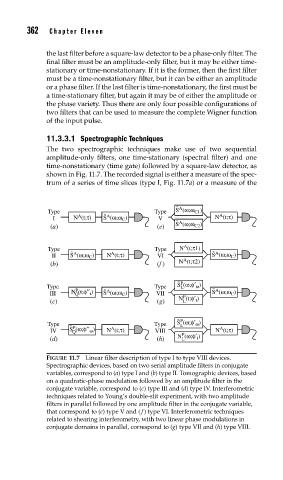
FIGURE 11.7 Linear filter description of type I to type VIII devices.
Spectrographic devices, based on two serial amplitude filters in conjugate
variables, correspond to (a) type I and (b) type II. Tomographic devices, based
on a quadratic-phase modulation followed by an amplitude filter in the
conjugate variable, correspond to (c) type III and (d) type IV. Interferometric
techniques related to Young’s double-slit experiment, with two amplitude
filters in parallel followed by one amplitude filter in the conjugate variable,
that correspond to (e) type V and ( f ) type VI. Interferometric techniques
related to shearing interferometry, with two linear phase modulations in
conjugate domains in parallel, correspond to (g) type VII and (h) type VIII.