
Page 56 - Phase-Locked Loops Design, Simulation, and Applications
P. 56
MIXED-SIGNAL PLL ANALYSIS Ronald E. Best 41
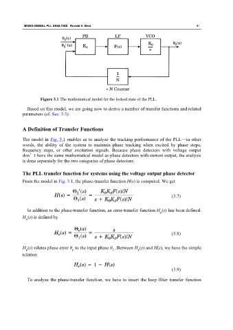
Figure 3.1 The mathematical model for the locked state of the PLL.
Based on this model, we are going now to derive a number of transfer functions and related
parameters (cf. Sec. 3.3).
A Definition of Transfer Functions
The model in Fig. 3.1 enables us to analyze the tracking performance of the PLL—in other
words, the ability of the system to maintain phase tracking when excited by phase steps,
frequency steps, or other excitation signals. Because phase detectors with voltage output
don’t have the same mathematical model as phase detectors with current output, the analysis
is done separately for the two categories of phase detectors.
The PLL transfer function for systems using the voltage output phase detector
From the model in Fig. 3.1, the phase-transfer function H(s) is computed. We get
(3.7)
In addition to the phase-transfer function, an error-transfer function H (s) has been defined.
e
H (s) is defined by
e
(3.8)
H (s) relates phase error θ to the input phase θ . Between H (s) and H(s), we have the simple
e
e
e
1
relation
(3.9)
To analyze the phase-transfer function, we have to insert the loop filter transfer function