
Page 60 - Phase-Locked Loops Design, Simulation, and Applications
P. 60
MIXED-SIGNAL PLL ANALYSIS Ronald E. Best 43
(The natural frequency ω must never be confused with the center frequency ω of the PLL.)
n 0
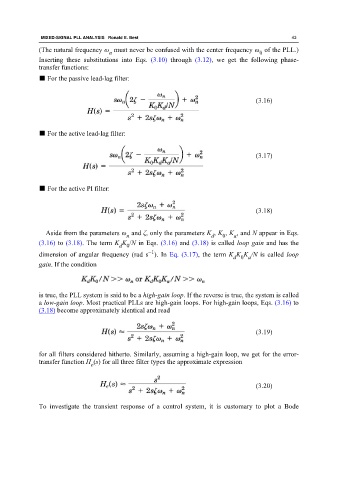
Inserting these substitutions into Eqs. (3.10) through (3.12), we get the following phase-
transfer functions:
■ For the passive lead-lag filter:
(3.16)
■ For the active lead-lag filter:
(3.17)
■ For the active PI filter:
(3.18)
Aside from the parameters ω and ζ, only the parameters K , K , K , and N appear in Eqs.
n d 0 a
(3.16) to (3.18). The term K K /N in Eqs. (3.16) and (3.18) is called loop gain and has the
d 0
−1
dimension of angular frequency (rad s ). In Eq. (3.17), the term K K K /N is called loop
d 0 a
gain. If the condition
is true, the PLL system is said to be a high-gain loop. If the reverse is true, the system is called
a low-gain loop. Most practical PLLs are high-gain loops. For high-gain loops, Eqs. (3.16) to
(3.18) become approximately identical and read
(3.19)
for all filters considered hitherto. Similarly, assuming a high-gain loop, we get for the error-
transfer function H (s) for all three filter types the approximate expression
e
(3.20)
To investigate the transient response of a control system, it is customary to plot a Bode