
Page 51 - Phase-Locked Loops Design, Simulation, and Applications
P. 51
MIXED-SIGNAL PLL BUILDING BLOCKS Ronald E. Best 36
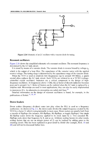
Figure 2.26 Schematic of an LC oscillator with a varactor diode for tuning.
Resonant oscillators
Figure 2.26 shows the simplified schematic of a resonant oscillator. The resonant frequency is
determined by the LC tank circuit.
It is tuned by means of a varactor diode. The varactor diode is reverse biased by voltage u ,
f
which is the output of a loop filter. The capacitance of the varactor varies with the applied
reserve voltage. The tuning range is determined by the capacitance range of the varactor diode.
When the VCO is used at relatively low frequencies (up to around 100 MHz), a quartz
crystal often replaces the LC tank circuit. Such VCOs are referred to as a VCXO (voltage-
controlled crystal oscillator). Inductors are a critical component in the design of high-
frequency oscillators. At frequencies above 1 GHz, the Q factor of discrete inductors becomes
poor and is around 2 to 3. Better Q factors can be realized when the LC tank is replaced by a
stripline stub. Microstrips are used in most applications; they can also be easily implemented
in microwave ICs. An alternative to microstrips are radial stub lines. 53
Detailed information on the design of resonant oscillators is found, for example, in the
publications of Rohde. 11, 48, 49
Down Scalers
Down scalers (frequency dividers) come into play when the PLL is used as a frequency
synthesizer. As shown in Fig. 2.1, the down scaler divides the output frequency created by the
VCO by a factor N, which is programmable in most cases. Down scalers are usually built from
a cascade of flipflops (for instance, RS-flipflops, JK-flipflops, or toggle flipflops). One single
JK-flipflop scales down the frequency applied to its clock input by 2. Two cascaded JK-
flipflops scale down that frequency by 4, and so on. Arbitrary scaling factors (in other words,
scaling factors that are not an integer power of 2) can be realized by adding gates to the
counting circuit. This has been explained in great detail by Rohde (for example, Refs. 10 and
48) and will not be discussed further here.