
Page 48 - Phase-Locked Loops Design, Simulation, and Applications
P. 48
MIXED-SIGNAL PLL BUILDING BLOCKS Ronald E. Best 34
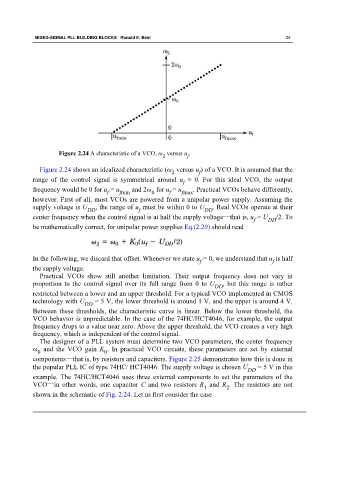
Figure 2.24 A characteristic of a VCO, ω versus u .
f
2
Figure 2.24 shows an idealized characteristic (ω versus u ) of a VCO. It is assumed that the
2 f
range of the control signal is symmetrical around u = 0. For this ideal VCO, the output
f
frequency would be 0 for u = u and 2ω for u = u . Practical VCOs behave differently,
f fmin 0 f fmax
however. First of all, most VCOs are powered from a unipolar power supply. Assuming the
supply voltage is U DD , the range of u must be within 0 to U DD . Real VCOs operate at their
f
center frequency when the control signal is at half the supply voltage—that is, u = U /2. To
f DD
be mathematically correct, for unipolar power supplies Eq.(2.29) should read
In the following, we discard that offset. Whenever we state u = 0, we understand that u is half
f f
the supply voltage.
Practical VCOs show still another limitation. Their output frequency does not vary in
proportion to the control signal over its full range from 0 to U , but this range is rather
DD
restricted between a lower and an upper threshold. For a typical VCO implemented in CMOS
technology with U DD = 5 V, the lower threshold is around 1 V, and the upper is around 4 V.
Between these thresholds, the characteristic curve is linear. Below the lower threshold, the
VCO behavior is unpredictable. In the case of the 74HC/HCT4046, for example, the output
frequency drops to a value near zero. Above the upper threshold, the VCO creates a very high
frequency, which is independent of the control signal.
The designer of a PLL system must determine two VCO parameters, the center frequency
ω and the VCO gain K . In practical VCO circuits, these parameters are set by external
0
0
components—that is, by resistors and capacitors. Figure 2.25 demonstrates how this is done in
the popular PLL IC of type 74HC/ HCT4046. The supply voltage is chosen U = 5 V in this
DD
example. The 74HC/HCT4046 uses three external components to set the parameters of the
VCO—in other words, one capacitor C and two resistors R and R . The resistors are not
1 2
shown in the schematic of Fig. 2.24. Let us first consider the case