
Page 44 - Phase-Locked Loops Design, Simulation, and Applications
P. 44
MIXED-SIGNAL PLL BUILDING BLOCKS Ronald E. Best 31
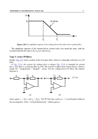
Figure 2.20 The amplitude response of the voltage-driven first-order active lead-lag filter.
The amplitude response of the current-driven version looks very much the same, with the
exception that the DC gain is R K now and not K .
1 a a
Type 3: Active PI filters
Finally, Fig. 2.21 shows another active low-pass filter, which is commonly referred to as a PI
filter.
In Fig. 2.21a, the version for voltage drive is shown; Fig. 2.21b is intended for current
drive. This filter is a lead-lag filter as well. The term PI is taken from control theory, where it
stands for “proportional + integral” action. For the voltage-driven PI filter, the transfer
function is
(2.31a)
where again τ = R C and τ = R C . The PI filter has a pole at s = 0 and therefore behaves
2 1
1
1 1
2
like an integrator. It has—at least theoretically—infinite gain at