
Page 47 - Phase-Locked Loops Design, Simulation, and Applications
P. 47
MIXED-SIGNAL PLL BUILDING BLOCKS Ronald E. Best 33
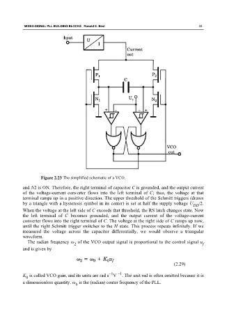
Figure 2.23 The simplified schematic of a VCO.
and N2 is ON. Therefore, the right terminal of capacitor C is grounded, and the output current
of the voltage-current converter flows into the left terminal of C; thus, the voltage at that
terminal ramps up in a positive direction. The upper threshold of the Schmitt triggers (drawn
by a triangle with a hysteresis symbol in its center) is set at half the supply voltage U /2.
DD
When the voltage at the left side of C exceeds that threshold, the RS latch changes state. Now
the left terminal of C becomes grounded, and the output current of the voltage-current
converter flows into the right terminal of C. The voltage at the right side of C ramps up now,
until the right Schmitt trigger switches to the H state. This process repeats infinitely. If we
measured the voltage across the capacitor differentially, we would observe a triangular
waveform.
The radian frequency ω of the VCO output signal is proportional to the control signal u
2 f
and is given by
(2.29)
−1
−1
K is called VCO gain, and its units are rad s V . The unit rad is often omitted because it is
0
a dimensionless quantity. ω is the (radian) center frequency of the PLL.
0