
Page 49 - Phase-Locked Loops Design, Simulation, and Applications
P. 49
MIXED-SIGNAL PLL BUILDING BLOCKS Ronald E. Best 35
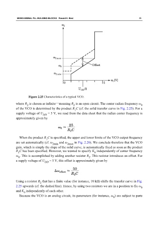
Figure 2.25 Characteristics of a typical VCO.
where R is chosen as infinite—meaning R is an open circuit. The center radian frequency ω
2 2 0
of the VCO is determined by the product R C (cf. the solid transfer curve in Fig. 2.25). For a
1
supply voltage of U = 5 V, we read from the data sheet that the radian center frequency is
DD
approximately given by
When the product R C is specified, the upper and lower limits of the VCO output frequency
1
are set automatically (cf. ω and ω in Fig. 2.20). We conclude therefore that the VCO
2min 2max
gain, which is simply the slope of the solid curve, is automatically fixed as soon as the product
R C has been specified. However, we wanted to specify K independently of center frequency
0
1
ω . This is accomplished by adding another resistor R . This resistor introduces an offset. For
0 2
a supply voltage of U DD = 5 V, this offset is approximately given by
Using a resistor R that has a finite value (for instance, 10 kΩ) shifts the transfer curve in Fig.
2
2.25 upwards (cf. the dashed line). Hence, by using two resistors we are in a position to fix ω
0
and K independently of each other.
0
Because the VCO is an analog circuit, its parameters (for instance, ω ) are subject to parts
0