
Page 46 - Phase-Locked Loops Design, Simulation, and Applications
P. 46
MIXED-SIGNAL PLL BUILDING BLOCKS Ronald E. Best 32
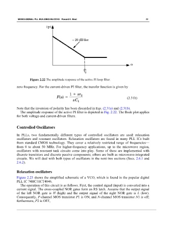
Figure 2.22 The amplitude response of the active PI loop filter.
zero frequency. For the current-driven PI filter, the transfer function is given by
(2.31b)
Note that the inversion of polarity has been discarded in Eqs. (2.31a) and (2.31b).
The amplitude response of the active PI filter is depicted in Fig. 2.22. The Bode plot applies
for both voltage-and current-driven filters.
Controlled Oscillators
In PLLs, two fundamentally different types of controlled oscillators are used: relaxation
oscillators and resonant oscillators. Relaxation oscillators are found in many PLL ICs built
from standard CMOS technology. They cover a relatively restricted range of frequencies—
from 0 to about 50 MHz. For higher-frequency applications, up to the microwave region,
oscillators with resonant tank circuits come into play. Some of these are implemented with
discrete transistors and discrete passive components; others are built as microwave-integrated
circuits. We will deal with both types of oscillators in the next two sections (Secs. 2.6.1 and
2.6.2).
Relaxation oscillators
Figure 2.23 shows the simplified schematic of a VCO, which is found in the popular digital
PLL IC 74HC/HCT4046.
The operation of this circuit is as follows. First, the control signal (input) is converted into a
current signal. The cross-coupled NOR gates form an RS latch. Assume that the output signal
of the left NOR gate is H (high) and the output signal of the right NOR gate is L (low).
Consequently, P-channel MOS transistor P1 is ON, and N-channel MOS transistor N1 is off;
furthermore, P2 is OFF,