
Page 43 - Phase-Locked Loops Design, Simulation, and Applications
P. 43
MIXED-SIGNAL PLL BUILDING BLOCKS Ronald E. Best 30
Figure 2.18 The amplitude response of first-order passive lead-lag filters. (a) A voltage-
driven loop filter. (b) A current-driven loop filter.
Type 2: Active lead-lag filters
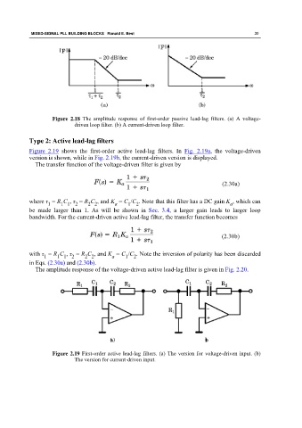
Figure 2.19 shows the first-order active lead-lag filters. In Fig. 2.19a, the voltage-driven
version is shown, while in Fig. 2.19b, the current-driven version is displayed.
The transfer function of the voltage-driven filter is given by
(2.30a)
where τ = R C , τ = R C , and K = C /C . Note that this filter has a DC gain K , which can
2 2
2
2
a
a
1
1 1
1
be made larger than 1. As will be shown in Sec. 3.4, a larger gain leads to larger loop
bandwidth. For the current-driven active lead-lag filter, the transfer function becomes
(2.30b)
with τ = R C , τ = R C , and K = C /C . Note the inversion of polarity has been discarded
1
2
1
2 2
2
a
1 1
in Eqs. (2.30a) and (2.30b).
The amplitude response of the voltage-driven active lead-lag filter is given in Fig. 2.20.
Figure 2.19 First-order active lead-lag filters. (a) The version for voltage-driven input. (b)
The version for current-driven input.