
Page 56 - Photodetection and Measurement - Maximizing Performance in Optical Systems
P. 56
Fundamental Noise Basics and Calculations
Fundamental Noise Basics and Calculations 49
mA
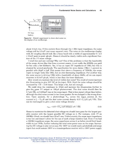
I = 1
p
Photodiode
1V
1M Oscilloscope
and display
9V bias
battery
Figure 3.2 (Failed) experiment to show shot noise on
the display of an oscilloscope.
about 2.5nA rms. If this current flows through the 1-MW input impedance, the noise
voltage will be 2.5mV root mean squared (rms). The noise on the oscilloscope display
with AC coupling should look like a fuzzy band with a width of approximately 6 ¥ 2.5
= 15mV peak-to-peak (pk-pk). Hence it should be clearly visible and a significant frac-
tion of the 1V mean voltage.
I tried this and saw nothing! Why not? One of the problems is that the bandwidth
of the scope, driven like this from a current source, is not really the 20MHz you paid
for but only a few kilohertz. Yes, it has an input DC impedance of 1MW, but this is
shunted by several picofarads. The specification for mine claims 1MW± 1 percent in
parallel with 20pF ± 2pF. This means that above a frequency of 7958Hz, the scope
input no longer looks like 1MW, but an ever-decreasing impedance. Put another way,
the noise source is driving 1MW with a bandwidth of about 8kHz; all we can expect
onscreen is 0.3mV pk-pk, which is less than the trace thickness.
How would you increase the level of visible shot noise? You could of course increase
the illumination to give 10V DC at the input. With 10mA the noise voltage should be
increased by 10 = 3.16 times. This helps a bit, but not enough.
We could drop the resistance to 10kW and increase the illumination further to
give the same 1V output or 100mA photocurrent. The shot noise should then be
5.7pA/ Hz , or 0.255mV rms at the scope input. That is less signal voltage than before,
although the shot noise current is ten times greater. So we changed in the wrong direc-
tion. Upon analysis, for a photovoltage V DC across the input resistor R, the
)
(
current is I p = V DC/R and the shot noise current density 057. I p mApA Hz . This
can be rearranged to give a shot noise voltage density:
R k ))
(
.
v shot = 057 ( V DC mV) ( W nV Hz (3.6)
Hence to maximize the detected shot voltage we should have gone for the largest pos-
sible resistor with the largest possible DC voltage on it. For instance, with 1V on
100MW (10nA) we should have 25mV rms. Unfortunately, the scope input impedance
is too low and doesn’t allow for the use of such a large resistive load. Even if we had
a 100MW impedance scope, the same capacitance across it as before would limit band-
width to just 79Hz, further reducing the total noise power seen on the scope. Increas-
ing the DC voltage is also not so easy. For 100V we would need a photodiode and scope
input that could sustain 100V or a transimpedance receiver with a 100V power supply
Downloaded from Digital Engineering Library @ McGraw-Hill (www.digitalengineeringlibrary.com)
Copyright © 2004 The McGraw-Hill Companies. All rights reserved.
Any use is subject to the Terms of Use as given at the website.