
Page 88 - Photodetection and Measurement - Maximizing Performance in Optical Systems
P. 88
Interlude: Alternative Circuits and Detection Techniques
Interlude: Alternative Circuits and Detection Techniques 81
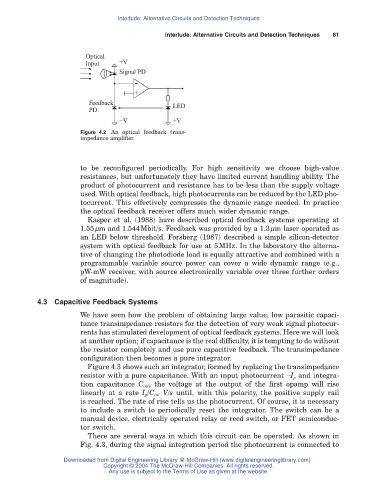
Optical
Input +V
Signal PD
-
Feedback + LED
PD
-V +V
Figure 4.2 An optical feedback trans-
impedance amplifier.
to be reconfigured periodically. For high sensitivity we choose high-value
resistances, but unfortunately they have limited current handling ability. The
product of photocurrent and resistance has to be less than the supply voltage
used. With optical feedback, high photocurrents can be reduced by the LED pho-
tocurrent. This effectively compresses the dynamic range needed. In practice
the optical feedback receiver offers much wider dynamic range.
Kasper et al. (1988) have described optical feedback systems operating at
1.55mm and 1.544Mbit/s. Feedback was provided by a 1.3mm laser operated as
an LED below threshold. Forsberg (1987) described a simple silicon-detector
system with optical feedback for use at 5MHz. In the laboratory the alterna-
tive of changing the photodiode load is equally attractive and combined with a
programmable variable source power can cover a wide dynamic range (e.g.,
pW-mW receiver, with source electronically variable over three further orders
of magnitude).
4.3 Capacitive Feedback Systems
We have seen how the problem of obtaining large value, low parasitic capaci-
tance transimpedance resistors for the detection of very weak signal photocur-
rents has stimulated development of optical feedback systems. Here we will look
at another option; if capacitance is the real difficulty, it is tempting to do without
the resistor completely and use pure capacitive feedback. The transimpedance
configuration then becomes a pure integrator.
Figure 4.3 shows such an integrator, formed by replacing the transimpedance
resistor with a pure capacitance. With an input photocurrent -I p and integra-
tion capacitance C int, the voltage at the output of the first opamp will rise
linearly at a rate I p /C int V/s until, with this polarity, the positive supply rail
is reached. The rate of rise tells us the photocurrent. Of course, it is necessary
to include a switch to periodically reset the integrator. The switch can be a
manual device, electrically operated relay or reed switch, or FET semiconduc-
tor switch.
There are several ways in which this circuit can be operated. As shown in
Fig. 4.3, during the signal integration period the photocurrent is connected to
Downloaded from Digital Engineering Library @ McGraw-Hill (www.digitalengineeringlibrary.com)
Copyright © 2004 The McGraw-Hill Companies. All rights reserved.
Any use is subject to the Terms of Use as given at the website.