
Page 89 - Photodetection and Measurement - Maximizing Performance in Optical Systems
P. 89
Interlude: Alternative Circuits and Detection Techniques
82 Chapter Four
Reset switch
Integration
capacitor
Sample C
switch int Readout
switch
I p - + V o
C h -
+
FET OpAmp
ON
Sample switch
OFF
Readout switch
Reset switch
Signal integration Signal integration
period (n) period (n+1)
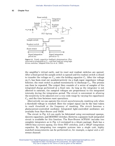
Figure 4.3 Purely capacitive feedback photoreceiver. Pho-
tocurrent is integrated on C int , and then read out using logic
driven switches. Adapted from Liu et al. (1993).
the amplifier’s virtual earth, and its reset and readout switches are opened.
After a fixed period the sample switch is opened and the readout switch is closed
to transfer the voltage on C int onto the holding capacitor C h . After the voltage
on C h has been read out nondestructively via a high input impedance voltage
follower, the reset switch is pulsed momentarily to discharge C int . The process
can then be repeated. The output then consists of a series of samples of the
integrated charge performed at a fixed rate. As long as the integrator is not
allowed to saturate, the sampled voltages are proportional to the integrated
intensity during the integration period. The circuit is convenient in allowing
the sensitivity to be adjusted over a very wide range by varying the capacitance
C int and the time between reset operations.
Alternatively we can operate the circuit asynchronously, resetting only when
a threshold voltage is reached. Here the output signal can be the time taken
to reach threshold or the frequency of resetting. The circuit becomes a
photocurrent-controlled oscillator. Integrated light-controlled oscillators are
available from Burr-Brown and TAOS.
The circuit in Fig. 4.3 can easily be fabricated using conventional opamps,
discrete capacitors, and MOSFET switches. However, a purpose-built integrated
circuit is available for this function. The Burr-Brown ACF2101 includes two
complete integrators as in Fig. 4.3 contained in a 24-pin package. Each has a
100-fA bias current opamp, the three FET switches, and a 100pF integration
capacitor. By integrating two complete systems into a single unit, highly
matched measurements can be performed on, for example, a signal and a ref-
erence channel.
Downloaded from Digital Engineering Library @ McGraw-Hill (www.digitalengineeringlibrary.com)
Copyright © 2004 The McGraw-Hill Companies. All rights reserved.
Any use is subject to the Terms of Use as given at the website.