
Page 98 - Photodetection and Measurement - Maximizing Performance in Optical Systems
P. 98
Interlude: Alternative Circuits and Detection Techniques
Interlude: Alternative Circuits and Detection Techniques 91
(a) (b) To detector
Probe beam Probe beam
(interferometer)
Detector Single-mode fiber
interferometer
Beam-splitter
Beam-splitter (fiber-end)
Meniscus
Thermal
expansion
Absorbed Absorbed
beam beam
Transparent
Liquid windows
under test
(c) (d)
Split photodiode Split photodiode
detector Absorbed detector
beam
A
Probe beam
B
Refracted
probe beam
Absorbed beam
(into page)
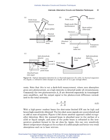
Figure 4.10 Optical absorption detection by (a) thermal expansion of a solid, (b) thermal expansion
of a liquid, (c) refractive index changes in a liquid, and (d) in a gas (mirage effect).
rents. Note that this is not a dark-field measurement, where zero absorption
gives zero photocurrent, as a high intensity is detected under all circumstances.
Commonly the two photocurrents A, B are detected separately in transimped-
ance amplifiers, and the output signal is the photocurrent difference normal-
ized to the total intensity:
A - B
S = (4.3)
+
AB
With a high-power readout beam the shot-noise limited S/N can be high and
hence high sensitivity obtained. The two shot-noise signals are uncorrelated and
so add as sum-of-squares. Figure 4.10d shows another approach called mirage-
effect detection. Here the scanned beam is absorbed near to the surface of a
solid or liquid sample, and some of the probe beam is refracted in the tem-
perature gradient formed in the air close by. Again, this can very sensitively
detect temperature changes at the surface of a solid sample and hence very weak
absorptions such as in laser mirrors.
Downloaded from Digital Engineering Library @ McGraw-Hill (www.digitalengineeringlibrary.com)
Copyright © 2004 The McGraw-Hill Companies. All rights reserved.
Any use is subject to the Terms of Use as given at the website.