
Page 101 - Photodetection and Measurement - Maximizing Performance in Optical Systems
P. 101
System Noise and Synchronous Detection
94 Chapter Five
optical power to a frequency above this range is usually preferable, and is the
job of modulation.
5.2 Modulation and Synchronous Detection
Instead of working DC with a photoreceiver connected to a voltmeter, in a mod-
ulated system the light source must be modulated, for example in intensity, and
only the detected AC signal measured. Where the source is a simple one, such
as a light-emitting diode (LED) or laser diode, modulation is usually straight-
forward to arrange. Simply connecting an LED via a current-limiting resistor
to an audio-frequency, square-wave, or pulse generator will effectively modu-
late the LED’s light output. If the generator output is bipolar, it is safer to
connect a silicon diode in inverse parallel with the LED to avoid exceeding the
latter’s reverse voltage limitation. If sinusoidal modulation is desired, the LED
should be biased with a DC current of about half its maximum current and
modulated about this current. Chapter 6 gives a few guidelines on these
practicalities.
The detected, buffered signal may be viewed and measured visually using an
oscilloscope, or after AC coupling using the AC voltage ranges of a standard
voltmeter. Most analog and digital voltmeters will still measure an AC signal at
a frequency up to a few hundred hertz or so, giving an average or rms reading
depending on the circuitry and calibration. This may be an adequate approach
if the signal is strong and the signal-to-noise (S/N) high. However, the AC volt-
meter, with its ill-defined and probably wide detection bandwidth, does not
make best use of the properties of the modulated light source. For better per-
formance and flexibility in choice of detection bandwidth one should use syn-
chronous detection.
“Synchronous detection” is a fancy name for changing the source intensity
and then looking for the change in detected output you expect to see; this is a
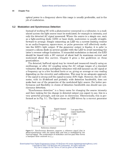
very powerful principle, and not just in electronics. Electronically, this is per-
formed as in Fig. 5.1. The figure shows an LED driven by a current generator
Losses
DC bias
Signal channel Low-pass filter,
f mod output bandwidth:
Demod r 1/2pRC
x
-
Source + DC R
LED Block C
Reference channel
Figure 5.1 Synchronous detection requires a reference signal that is
phase-synchronous with the signal light and that is multiplied by the
received signal. The combination of modulator and low-pass filter forms
a bandpass filter centered on f mod .
Downloaded from Digital Engineering Library @ McGraw-Hill (www.digitalengineeringlibrary.com)
Copyright © 2004 The McGraw-Hill Companies. All rights reserved.
Any use is subject to the Terms of Use as given at the website.