
Page 81 - Photonics Essentials an introduction with experiments
P. 81
Electrical Response Time of Diodes
Electrical Response Time of Diodes 75
Problems
(Refer to Chapter 11, laboratory exercise 11.2.) In the laboratory, you
will use lenses (consult Chapter 10, Sections 10.1 and 10.2) to control
the incident light beam and a lock-in amplifier to detect a modulated
light beam that is incident on the photodiode. The lock-in amplifier al-
lows you to make reliable measurments even when the room lights
are on. (Consult Chapter 10, Sections 10.6, 10.7, and 10.8 for more in-
formation.)
4.1 You are responsible for the design of a photodetector for an opti-
cal fiber telecommunications link at the = 1300 nm low-loss re-
gion for optical fiber transmission.
a. You have the choice between silicon or germanium photodi-
odes. Which is the better choice? Explain your answer?
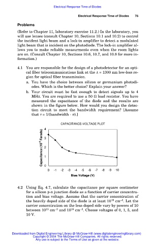
b. Your circuit must be fast enough to detect signals up to 4
MHz. You are required to use a 50 load resistor. You have
measured the capacitance of the diode and the results are
shown in the figure below. How would you design the detec-
tion circuit to meet the bandwidth requirement? [Assume
that = 1/(bandwidth · ).]
CAPACITANCE–VOLTAGE PLOT
4.2 Using Eq. 4.7, calculate the capacitance per square centimeter
for a silicon p-n junction diode as a function of carrier concentra-
tion and bias voltage. Assume that the carrier concentration of
–3
the heavily doped side of the diode is at least 10 19 cm . Let the
carrier concentration on the less-doped side vary by powers of 10
–3
between 10 15 cm –3 and 10 18 cm . Choose voltages of 0, 1, 5, and
10 V.
Downloaded from Digital Engineering Library @ McGraw-Hill (www.digitalengineeringlibrary.com)
Copyright © 2004 The McGraw-Hill Companies. All rights reserved.
Any use is subject to the Terms of Use as given at the website.