
Page 78 - Photonics Essentials an introduction with experiments
P. 78
Electrical Response Time of Diodes
72 Photonic Devices
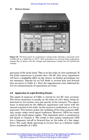
Figure 4.6. The front panel of a capacitance–voltage meter showing a measured value
of 199.2 pF at a diode bias of 100 V. This instrument can measure both conductance
(charge flow in phase with the voltage) and capacitance (charge flow 90° behind the
voltage).
pacitance of the diode leads. This is on the order of a few picofarads. If
the diode capacitance is greater than 100 pF, this stray capacitance
will have a negligible effect on the results, so further precautions are
not necessary. Results for an InP diode in reverse bias and forward
bias are given in Table 4.1. Note the experimental error indicated by
the two measurements of capacitance at 0 bias:
4.8 Application to Light-Emitting Diodes
The speed of response of LEDs is limited by the RC time constant.
The series resistance is usually on the order of a few ohms, being de-
termined by the surface area and quality of the contacts. The capaci-
tance is dominated by the diffusion capacitance and varies with the
current injected in the diode. As the current is modulated, so is the ca-
pacitance. This feature makes the modeling of the time response diffi-
cult, except under small signal conditions. However, LEDs are rarely
used in the small-signal regime. This important point is examined in
full detail in Chapter 6. The result is that typical commercial LED
has a frequency cut-off in forward bias on the order of a few mega-
hertz. The same diode operating in reverse bias as a detector might
have a bandwidth of 1 GHz.
Downloaded from Digital Engineering Library @ McGraw-Hill (www.digitalengineeringlibrary.com)
Copyright © 2004 The McGraw-Hill Companies. All rights reserved.
Any use is subject to the Terms of Use as given at the website.