
Page 287 - Physical Principles of Sedimentary Basin Analysis
P. 287
8.5 Fracture 269
σ 1
σ 3 σ 3
σ 3 σ 3
θ
(b)
σ 1
(a)
◦
Figure 8.10. (a) Shear fracture making an angle θ ≈ 60 produced by a triaxial test. (b) Tension
fracture that is normal to the least principal stress (σ 3 ).
τ τ
τ
S 0 φ 2θ φ 3 2 1
σ 3 σ σ 1 σ σ
σ = σ
1 Μ
σ = − T 0
3
(a) (b)
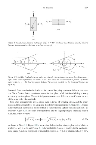
Figure 8.11. (a) The Coulomb fracture criterion gives the stress states for fracture by a linear enve-
lope. Stress states represented by Mohr’s circles that touch the envelope lead to failure. (b) Stress
states with σ 3 =−T 0 lead to tension failure. The largest possible σ 1 for tensional fracture is
σ 1 = σ M .
Coulomb fracture criterion is similar to Amontons’ law, they represent different phenom-
ena. Shear fracture is the creation of a new fracture plane, while frictional sliding is along
an already existing plane. The material parameters are also different, even if μ and μ 0 are
of the same order of magnitude.
It is often convenient to give a stress state in terms of principal stress, and the shear
stress and the normal stress on any plane then follow from relations (8.3) and (8.4). Stress
states that touch the fracture envelope lead to failure (along a plane with orientation θ)as
shown in Figure 8.11. The least principal stress and the largest principal stress are related
at failure, where we have
!
!
2 2
1 + μ − μ 0 σ 1 = 1 + μ + μ 0 σ 3 + 2S 0 (8.26)
0 0
as shown in Note 8.1. Figure 8.11a shows that failure is then along a plane oriented at an
angle θ = π/4 + φ/2, and Figure 3.11 shows that the θ-angle is relative to the least prin-
◦
cipal stress. A typical coefficient of internal friction is μ 0 ≈ 0.6 or alternatively φ ≈ 30 ,