
Page 288 - Physical Principles of Sedimentary Basin Analysis
P. 288
270 Rheology: fracture and flow
hanging wall hanging wall
θ = 60°
footwall
θ = 30° footwall
(a) normal fault (b) reverse (thrust) fault
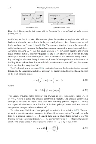
Figure 8.12. The angles the fault makes with the horizontal for a normal fault (a) and a reverse
(thrust) fault (b).
which implies that θ ≈ 60 . The fracture plane then makes an angle ∼ 60 with the
◦
◦
horizontal when the overburden is the largest principal stress. Such fractures are normal
faults as shown by Figures 8.1 and 8.12a. The opposite situation is when the overburden
is the least principal stress and the lateral compressive stress is the largest principal stress.
◦
Assuming the same μ 0 ≈ 0.6 then gives an angle θ ≈ 30 . Such fractures are reverse
faults or thrust faults as shown by Figures 8.1 and 8.12b. This use of a Coulomb fracture
envelope to explain the different types of faults is referred to as Anderson’s theory of fault-
ing. Although Anderson’s theory is not exact, it nevertheless explains the main features of
◦
faulting. Observations show that normal faults are often steeper than 60 , and that reverse
◦
faults are often less steep than 30 .
The Coulomb fracture envelope (8.26) relates the least and the largest principal stress at
failure, and the largest principal stress necessary for fracture is the following linear function
of the least principal stress:
2
!
2
σ 1 = 1 + μ + μ 0 σ 3 + C 0 (8.27)
0
where
!
2
C 0 = 2S 0 1 + μ + μ 0 . (8.28)
0
The largest principal stress necessary for fracture at zero compressive stress (σ 3 )is
σ 1 = C 0 , which is called the uniaxial compressive strength. The uniaxial compressive
strength is measured in triaxial tests with zero confining pressure. Figure 8.13 shows
the largest principal stress as a function of the least principal stress, with the uniaxial
compressive strength and the tension cutoff.
There is a lower limit for the least principal stress in the linear relation (8.27). The case
of tension (negative confining pressure) is different from compression. The rock normally
fails for a negative stress σ 3 =−T 0 , and it fails along a plane that is normal to σ 3 .The
fracture envelope therefore stops at σ 3 =−T 0 as shown in Figure 8.11, which is the tension
cutoff. The largest stress σ 1 that is possible with σ 3 =−T 0 is σ 1 = σ M , where
C 0 T 0
σ M = C 0 1 − 2 . (8.29)
4S
0