
Page 70 - Physical Principles of Sedimentary Basin Analysis
P. 70
52 Linear elasticity and continuum mechanics
τ
|τ| (σ , −τ)
xx
2θ σ
σ 3 σ n σ 1
(σ , τ)
zz
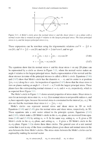
Figure 3.11. A Mohr’s circle gives the normal stress σ and the shear stress τ on a plane with a
normal vector that is rotated an angle θ relative to the largest principal stress. The least principal
stress is σ 3 and the largest principal stress is σ 1 .
2 1
These expressions can be rewritten using the trigonometric relations cos θ = (1 +
2
2
1
cos 2θ),sin θ = (1 − cos 2θ) and sin 2θ = 2sin θ cos θ, and we get
2
1 1
σ = (σ 1 + σ 3 ) + (σ 1 − σ 3 ) cos 2θ (3.66)
2 2
1
τ =− (σ 1 − σ 3 ) sin 2θ. (3.67)
2
The equations show that the normal stress σ and the shear stress τ on any 2D plane can
be represented by a circle as shown in Figure 3.11, where the normal vector makes an
angle θ relative to the largest principal stress. Such a representation of the normal and the
shear stresses in terms of the principal stresses is called a Mohr’s circle. Equations (3.66)
and (3.67) show that Mohr’s circle has the diameter σ 1 − σ 3 and its center is at position
1 (σ 1 +σ 3 ) along the σ-axis. An inspection of equation (3.67) shows that the shear stress is
2
zero on planes making an angle θ = 0or θ = π/2 with the largest principal stress. These
planes have the corresponding normal stresses σ = σ 1 and σ = σ 3 , respectively, which is
as expected from Figure 3.11.
The Mohr’s circle in Figure 3.11 shows several properties of stress states. Shear stress is
zero for an isotropic stress state (σ 1 = σ 3 ). Zero normal stress is not possible unless σ 1 and
σ 3 have opposite signs, because the normal stress is constrained to the interval [σ 3 ,σ 1 ].We
1
also see that the maximum shear stress is τ = (σ 1 − σ 3 ).
2
Mohr’s circles can represent normal stress and shear stress in 3D as well.
Equations (3.48) and (3.49) give the normal stress and shear stress, respectively, in 3D.
These equations take a unit vector related to the principle system. Equations (3.64)
and (3.65), which make a 2D Mohr’s circle in the σ 1 –σ 3 -plane, are recovered from equa-
tions (3.48) and (3.49) by setting n 2 = 0. In the same way, setting n 1 = 0, gives a 2D
Mohr’s circle in the σ 2 –σ 3 -plane, and setting n 3 = 0 gives a 2D Mohr’s circle in the
σ 1 –σ 2 -plane. Figure 3.12a shows these three circles. The general case of a unit normal
vector that is not in any of the three coordinate planes gives shear and normal stress in the
area between the three Mohr’s circles. The stress states between the Mohr’s circles can be
explored by making the normal vector
n 1 = cos α cos β, n 2 = cos α sin β, n 3 = sin α (3.68)