
Page 72 - Physical Principles of Sedimentary Basin Analysis
P. 72
54 Linear elasticity and continuum mechanics
f i = σ ij n j A (3.73)
where A is the area of the plane. Section 3.7 shows that it is always possible to choose
a coordinate system where the stress tensor becomes diagonal. The diagonal elements σ ii
are the principal stresses denoted σ i , and the force expressed in the principal coordinate
system is
f 1 = σ 1 n 1 A, f 2 = σ 2 n 2 A, f 3 = σ 3 n 3 A, (3.74)
and the force vector divided by the area A is the stress vector S = f/A. The stress vector
on planes with all possible orientations can now be represented by a stress ellipsoid. The
normal vector n has length 1:
2
2
2
n · n = n + n + n = 1 (3.75)
1 2 3
and the components (3.74) of the force vector give the components of the unit vector,
S 1 S 2 S 3
n 1 = , n 2 = , n 3 = . (3.76)
σ 1 σ 2 σ 3
This unit vector is inserted into expression (3.75) for unit length
2
2
2
S 1 S 2 S 3
+ + = 1 (3.77)
σ 1 σ 2 σ 3
which is the equation for an ellipsoid. For a given stress tensor (σ 1 , σ 2 and σ 3 ) the stress
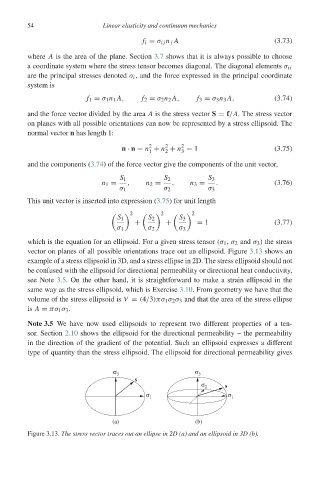
vector on planes of all possible orientations trace out an ellipsoid. Figure 3.13 shows an
example of a stress ellipsoid in 3D, and a stress ellipse in 2D. The stress ellipsoid should not
be confused with the ellipsoid for directional permeability or directional heat conductivity,
see Note 3.5. On the other hand, it is straightforward to make a strain ellipsoid in the
same way as the stress ellipsoid, which is Exercise 3.10. From geometry we have that the
volume of the stress ellipsoid is V = (4/3)πσ 1 σ 2 σ 3 and that the area of the stress ellipse
is A = πσ 1 σ 3 .
Note 3.5 We have now used ellipsoids to represent two different properties of a ten-
sor. Section 2.10 shows the ellipsoid for the directional permeability – the permeability
in the direction of the gradient of the potential. Such an ellipsoid expresses a different
type of quantity than the stress ellipsoid. The ellipsoid for directional permeability gives
σ 3 σ 3
s
σ 2 s
σ 1 σ 1
(a) (b)
Figure 3.13. The stress vector traces out an ellipse in 2D (a) and an ellipsoid in 3D (b).