
Page 71 - Physical Principles of Sedimentary Basin Analysis
P. 71
3.9 Stress ellipsoid 53
τ σ 3
3 n 3
n
[MPa] 2 7 6 5 4 3 α n
1 5 8 β 2 β 2 σ 2
7 6 4 3 1
8 α 2 9 n
9 1 1
0 10 0 10 0 σ σ 1
1 2 3 4 5 6 7
σ 3 σ 2 [MPa] σ 1
(a) (b)
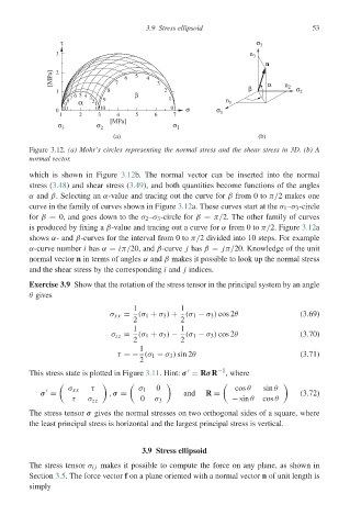
Figure 3.12. (a) Mohr’s circles representing the normal stress and the shear stress in 3D. (b) A
normal vector.
which is shown in Figure 3.12b. The normal vector can be inserted into the normal
stress (3.48) and shear stress (3.49), and both quantities become functions of the angles
α and β. Selecting an α-value and tracing out the curve for β from 0 to π/2 makes one
curve in the family of curves shown in Figure 3.12a. These curves start at the σ 1 –σ 3 -circle
for β = 0, and goes down to the σ 2 –σ 3 -circle for β = π/2. The other family of curves
is produced by fixing a β-value and tracing out a curve for α from 0 to π/2. Figure 3.12a
shows α- and β-curves for the interval from 0 to π/2 divided into 10 steps. For example
α-curve number i has α = iπ/20, and β-curve j has β = jπ/20. Knowledge of the unit
normal vector n in terms of angles α and β makes it possible to look up the normal stress
and the shear stress by the corresponding i and j indices.
Exercise 3.9 Show that the rotation of the stress tensor in the principal system by an angle
θ gives
1 1
σ xx = (σ 1 + σ 3 ) + (σ 1 − σ 3 ) cos 2θ (3.69)
2 2
1 1
σ zz = (σ 1 + σ 3 ) − (σ 1 − σ 3 ) cos 2θ (3.70)
2 2
1
τ =− (σ 1 − σ 3 ) sin 2θ (3.71)
2
This stress state is plotted in Figure 3.11. Hint: σ = RσR −1 , where
σ xx τ σ 1 0 cos θ sin θ
σ = , σ = and R = (3.72)
τ σ zz 0 σ 3 − sin θ cos θ
The stress tensor σ gives the normal stresses on two orthogonal sides of a square, where
the least principal stress is horizontal and the largest principal stress is vertical.
3.9 Stress ellipsoid
The stress tensor σ ij makes it possible to compute the force on any plane, as shown in
Section 3.5. The force vector f on a plane oriented with a normal vector n of unit length is
simply