
Page 324 - Physical chemistry understanding our chemical world
P. 324
INTRODUCTION TO CELLS: TERMINOLOGY AND BACKGROUND 291
Why bother to draw cells?
Cells and the ‘cell schematic’
Having defined a cell, we now want to know the best way of representing it. Undoubt-
edly, the simplest is to draw it diagrammatically – no doubt each picture of a cell
being a work of art in miniature.
But drawing is laborious, so we generally employ a more sensible alternative: we
write a cell schematic, which is a convenient abbreviation of a cell. It can be ‘read’
as though it was a cross-section, showing each interface and phase. It is, therefore,
simply a shorthand way of saying which components are incorporated in the cell as
cathode, anode, electrolyte, etc., and where they reside.
Most people find that a correct understanding of how to write a cell schematic also
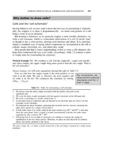
helps them understand the way a cell works. Accordingly, Table 7.2 contains a series
of simple rules for constructing the schematic.
Worked Example 7.4 We construct a cell with the copper(II) | copper and zinc(II) |
zinc redox couples, the copper couple being more positive than the zinc couple. What is
the cell schematic?
Answer strategy: we will work sequentially through the rules in Table 7.2.
First, we note how the copper couple is the most positive, so we
For convenience, we
write it on the right. The zinc is, therefore, the more negative and
we write it on the left. We commence the schematic by writing, often omit the subscript
Zn (s) .. . Cu (s) ⊕. descriptors and the ‘ ’
and ‘⊕’signs.
Table 7.2 Rules for constructing a cell schematic
1. We always write the redox couple associated with the positive electrode on the
right-hand side
2. We write the redox couple associated with the negative electrode on the left-hand side
3. We write a salt bridge as a double vertical line: ||
4. If one redox form is conductive and can function as an electrode, then we write it on one
extremity of the schematic.
5. We represent the phase boundary separating this electrode and the solution containing the
a
other redox species by a single vertical line: |
4+
6. If both redox states of a couple reside in the same solution (e.g. Pb 2+ and Pb ), then they
share the same phase. Such a couple is written conventionally with the two redox states
4+
separated by only a comma: Pb , Pb 2+
7. Following from 6: we see that no electrode is in solution to measure the energy at
equilibration of the two redox species. Therefore, we place an inert electrode in solution;
almost universally, platinum is the choice
a We write a single line | or, better, a dotted vertical line, if the salt bridge is replaced by a simple porous
membrane.