
Page 111 - Physical chemistry eng
P. 111
88 CHAPTER 5 Entropy and the Second and Third Laws of Thermodynamics
surroundings in the first two segments and on the system in the last two segments. An
engine is only useful if net work is done on the surroundings, that is, if the magnitude of the
work done in the first two steps is greater than the magnitude of the work done in the last
two steps. The efficiency of the engine can be calculated by comparing the net work per
cycle with the heat taken up by the engine from the hot reservoir.
Before carrying out this calculation, we discuss the rationale for the design of this
reversible cycle in more detail. To avoid losing heat to the surroundings at temperatures
between T hot and T cold , adiabatic segments 2 (b : c) and 4 (d : a) are used to move the
gas between these temperatures. To absorb heat only at T hot and release heat only at T cold ,
segments 1 (a : b) and 3 (c : d) must be isothermal. The reason for using alternating
isothermal and adiabatic segments is that no two isotherms at different temperatures inter-
sect, and no two adiabats starting from two different temperatures intersect. Therefore, it
is impossible to create a closed cycle of nonzero area in an indicator diagram out of
isothermal or adiabatic segments alone. However, net work can be done using alternating
adiabatic and isothermal segments. The reversible cycle depicted in Figure 5.2 is called a
Carnot cycle, after the French engineer who first studied such cycles.
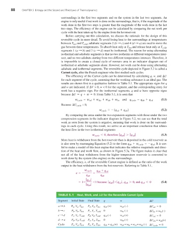
The efficiency of the Carnot cycle can be determined by calculating q, w, and ¢U
for each segment of the cycle, assuming that the working substance is an ideal gas. The
results are shown first in a qualitative fashion in Table 5.1. The appropriate signs for q
and w are indicated. If ¢V > 0, w < 0 for the segment, and the corresponding entry for
work has a negative sign. For the isothermal segments, q and w have opposite signs
because ¢U = q + w = 0 . From Table 5.1, it is seen that
w cycle = w cd + w da + w ab + w and q cycle = q ab + q cd (5.1)
bc
Because ¢U cycle = 0,
=- (q + q ) (5.2)
w cycle cd ab
By comparing the areas under the two expansion segments with those under the two
compression segments in the indicator diagram in Figure 5.2, we can see that the total
work as seen from the system is negative, meaning that work is done on the surround-
ings in each cycle. Using this result, we arrive at an important conclusion that relates
the heat flow in the two isothermal segments
w cycle 6 0, therefore ƒ q ƒ 7 ƒ q cd ƒ (5.3)
ab
More heat is withdrawn from the hot reservoir than is deposited in the cold reservoir as
is also seen by rearranging Equation (5.2) to the form q ab + w cycle =- q cd . It is use-
ful to make a model of this heat engine that indicates the relative magnitude and direc-
tion of the heat and work flow, as shown in Figure 5.3a. The figure makes it clear that
not all of the heat withdrawn from the higher temperature reservoir is converted to
work done by the system (the engine) on the surroundings.
e
The efficiency, , of the reversible Carnot engine is defined as the ratio of the work
output to the heat withdrawn from the hot reservoir. Referring to Table 5.1,
w cycle q + q
e =- = ab cd
q ab q ab
ƒ q ƒ
= 1- cd 61 because ƒ q ƒ 7 ƒ q ƒ , q ab 7 0, and q cd 6 0 (5.4)
ab
cd
ƒ q ab ƒ
TABLE 5.1 Heat, Work, and ¢U for the Reversible Carnot Cycle
Segment Initial State Final State q w ¢U
a : b P a , V a , T hot P b , V b , T hot q ab (+) w ab (–) ¢U ab = 0
b : c P b , V b , T hot P c , V c , T cold 0 w bc (–) ¢U bc = w bc (–)
c : d P c , V c , T cold P d , V d , T cold q cd (–) w cd (+) ¢U cd = 0
d : a P d , V d , T cold P a , V a , T hot 0 w da (+) ¢U da = w da (+)
Cycle P a , V a , T hot P a , V a , T hot q ab + q cd (+) w ab + w bc + w cd + w da (–) ¢U cycle = 0