
Page 110 - Physical chemistry eng
P. 110
5.2 HEAT ENGINES AND THE SECOND LAW OF THERMODYNAMICS 87
FIGURE 5.1
A schematic depiction of a heat engine is
T hot shown. Changes in temperature of the
working substance brought about by con-
tacting the cylinder with hot or cold reser-
voirs generate a linear motion that is
mechanically converted to a rotary
motion, which is used to do work.
T cold
of the water and the heater. What is the maximum theoretical efficiency of the reverse
process, the conversion of heat to work? As shown later, it is less than 100%. There is a
natural asymmetry in the efficiency of converting work to heat and converting heat to
work. Thermodynamics provides an explanation for this asymmetry.
As discussed in Section 2.7, the maximum work output in an isothermal expansion
occurs in a reversible process. For this reason, we next calculate the efficiency of a
reversible heat engine, because the efficiency of a reversible engine is an upper bound
to the efficiency of a real engine. This reversible engine converts heat into work by
exploiting the spontaneous tendency of heat to flow from a hot reservoir to a cold reser-
voir. It does work on the surroundings by operating in a cycle of reversible expansions
and compressions of an ideal gas in a piston and cylinder assembly. We discuss auto-
motive engines in Section 5.11.
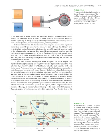
The cycle for a reversible heat engine is shown in Figure 5.2 in a P–V diagram. The
expansion and compression steps are designed so that the engine returns to its initial state
after four steps. Recall from Section 2.7 that the area within the cycle equals the work done
by the engine. As discussed later, four separate isothermal and adiabatic steps are needed to
make the enclosed area in the cycle greater than zero. Beginning at point a, the first segment
is a reversible isothermal expansion in which the gas absorbs heat from the reservoir at T ,
hot
and does work on the surroundings. In the second segment, the gas expands further, this
time adiabatically. Work is also done on the surroundings in this step. At the end of the sec-
ond segment, the gas has cooled to the temperature T cold . The third segment is an isother-
mal compression in which the surroundings do work on the system and heat is absorbed by
the cold reservoir. In the final segment, the gas is compressed to its initial volume, this time
adiabatically. Work is done on the system in this segment, and the temperature returns to
its initial value, T . In summary, heat is taken up by the engine in the first segment at
hot
T , and released to the surroundings in the third segment at T cold . Work is done on the
hot
a
P a Isothermal expansion
FIGURE 5.2
T hot
A reversible Carnot cycle for a sample of
Adiabatic
T cold an ideal gas working substance is shown
compression
Pressure on an indicator diagram. The cycle con-
sists of two adiabatic and two isothermal
P b T hot b Adiabatic expansion segments. The arrows indicate the direc-
T hot tion in which the cycle is traversed. The
T cold
Isothermal insets show the volume of gas and the
P d compression T cold coupling to the reservoirs at the beginning
d
T hot of each successive segment of the cycle.
P c c The coloring of the contents of the cylin-
T cold
der indicates the presence of the gas and
not its temperature. The volume of the
0 V a V d V b V c cylinder shown is that at the beginning of
Volume the appropriate segment.