
Page 54 - Physical chemistry eng
P. 54
2.8 COMPARING WORK FOR REVERSIBLE AND IRREVERSIBLE PROCESSES 31
returned to its initial value by an infinitesimal temperature decrease. This relationship
is characteristic of an irreversible process. Although any process that takes place at a
rapid rate in the real world is irreversible, real processes can approach reversibility in
the appropriate limit. For example, a slow increase in the electrical potential in an elec-
trochemical cell can convert reactants to products in a nearly reversible process.
Comparing Work for Reversible and
2.8 Irreversible Processes
We concluded in Section 2.6 that w is not a state function and that the work associated
with a process is path dependent. This statement can be put on a quantitative footing by
comparing the work associated with the reversible and irreversible expansion and the P 1
compression of an ideal gas. This process is discussed next and illustrated in Figure 2.14.
Consider the following irreversible process, meaning that the internal and external
pressures are not equal. A quantity of an ideal gas is confined in a cylinder with a weight-
less movable piston. The walls of the system are diathermal, allowing heat to flow P
between the system and surroundings. Therefore, the process is isothermal at the temper- P external 2
ature of the surroundings, T. The system is initially defined by the variables T, P , and V .
1
1
The position of the piston is determined by P external = P 1 , which can be changed by
adding or removing weights from the piston. Because the weights are moved horizontally,
no work is done in adding or removing them. The gas is first expanded at constant tem-
perature by decreasing P external abruptly to the value P (weights are removed), where
2
P 6 P 1 . A sufficient amount of heat flows into the system through the diathermal walls
2
to keep the temperature at the constant value T. The system is now in the state defined by
T, P , and V , where V 7 V 1 . The system is then returned to its original state in an 0 V V
2
2
2
isothermal process by increasing P external abruptly to its original value P (weights are 1 V 2
1
added). Heat flows out of the system into the surroundings in this step. The system has
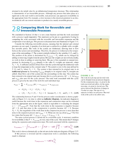
been restored to its original state and, because this is a cyclic process, ¢U = 0 . Are q total FIGURE 2.14
and w total also zero for the cyclic process? The total work associated with this cyclic The work for each step and the total work
process is given by the sum of the work for each individual step: can be obtained from an indicator diagram.
For the compression step, w is given by the
w total = - P external, i ¢V = w expansion + w compression total area in red and yellow; for the expan-
i
a
i sion step, w is given by the red area. The
arrows indicate the direction of change in
=-P (V - V ) - P (V - V ) V in the two steps. The sign of w is
2
2
1
2
1
1
=-(P - P ) * (V - V ) 7 0 because P 6 P andV 7 V 1 (2.19) opposite for these two processes. The total
1
1
2
2
1
2
2
work in the cycle is the yellow area.
The relationship between P and V for the process under consideration is shown graphi-
cally in Figure 2.14, in what is called an indicator diagram. An indicator diagram is
useful because the work done in the expansion and contraction steps can be evaluated
from the appropriate area in the figure, which is equivalent to evaluating the integral
w =- P external dV . Note that the work done in the expansion is negative because
1
¢V 7 0 , and that done in the compression is positive because ¢V 6 0 . Because
P 6 P 1 , the magnitude of the work done in the compression process is more than that
2
done in the expansion process and w total 7 0 . What can one say about q total ? The first
law states that because ¢U = q total + w total = 0 , q total 6 . 0
The same cyclical process is carried out in a reversible cycle. A necessary condition
for reversibility is that P = P external at every step of the cycle. This means that P changes
during the expansion and compression steps. The work associated with the expansion is
dV V 2
w expansion =- P external dV = - PdV =-nRT =-nRT ln (2.20)
V V 1
L L L
This work is shown schematically as the red area in the indicator diagram of Figure 2.15.
If this process is reversed and the compression work is calculated, the following
result is obtained:
V 1
w compression =-nRTln (2.21)
V 2