
Page 177 - Pipeline Pigging Technology
P. 177
Pipeline Pigging Technology
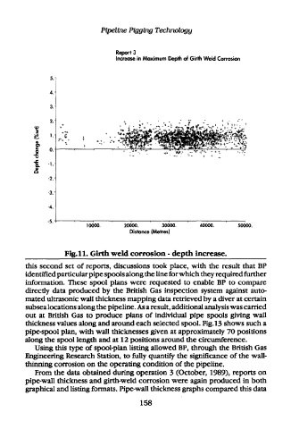
Report 3
Increase in Maximum Depth of Girth Weld Corrosion
10000. 20000. 30000. 40000. 50000.
Distance (Metres)
Fig. 11. Girth weld corrosion - depth increase.
this second set of reports, discussions took place, with the result that BP
identified particular pipe spools along the line for which they required further
information. These spool plans were requested to enable BP to compare
directly data produced by the British Gas inspection system against auto-
mated ultrasonic wall thickness mapping data retrieved by a diver at certain
subsea locations along the pipeline. As a result, additional analysis was carried
out at British Gas to produce plans of individual pipe spools giving wall
thickness values along and around each selected spool. Fig. 13 shows such a
pipe-spool plan, with wall thicknesses given at approximately 70 positions
along the spool length and at 12 positions around the circumference.
Using this type of spool-plan listing allowed BP, through the British Gas
Engineering Research Station, to fully quantify the significance of the wall-
thinning corrosion on the operating condition of the pipeline.
From the data obtained during operation 3 (October, 1989), reports on
pipe-wall thickness and girth-weld corrosion were again produced in both
graphical and listing formats. Pipe-wall thickness graphs compared this data
158