
Page 286 - Pipeline Pigging Technology
P. 286
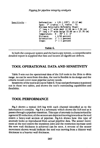
Pigging for pipeline integrity analysis


        Sensitivity  :         Deformation:  ± 1/8 (.125")  (3.17 mm)
                               Span:  7"  (radius +  2, radius - 5)
                               Minimum  Detectable  Deformity  Shape:
                               1" long x  1" wide dent  (2.54  cm  x 2.54 cm)
                               2" long  x 7" wide bulge (5.08 cm x 27.78  cm)
                               Temperature:  0  - 70* C ±  .5"
                               Distance:     ± 1/10 percent
                               Orientation:  1*  ±  1  percent
                               Slope:        1*  ±  1  percent


                                    Table 6.
        In both the computer system and the hard-copy system, a comprehensive
     detailed report is supplied that lists and locates all significant defects.


        TOOL OPERATIONAL DATA AND                     SENSITIVITY


        Table 5 sets out  the operational data of the D/S tools in the  20-in to 48-in
     range. As can be seen from  this data, the tool is flexible in its design and  the
     criteria would cover most pipeline survey needs.
        Sensitivity of the tool is set out in Table 6. Total tool performance is pointed
     out  in these  two  tables,  and  shows  the  tool's outstanding capabilities and
     flexibility.


        TOOL PERFORMANCE


        Fig. 3  shows  a  typical  D/S log with  each  channel  identified as  to  the
     information  it contains.  Fig.4 is a schematic which  shows  the  D/S tool  as it
     passes through a pipeline transition. This type of anomaly is characterized by
     a general ID reduction; all the sensors are depicted moving inwards as the tool
     enters  a  heavy-wall section  of  pipeline.  Fig.4-A  shows  how  this  type  of
     anomaly looks as reproduced  from  actual pipeline  data. The  sensor move-
     ment as the tool enters the transition joint and the restriction increase until
     the  new  wall  thickness  is achieved  can  be  seen.  A reverse  of  the  sensor
     movement shown would    indicate the  tool was moving from  a thinner wall
     thickness to a heavier wall  thickness.


                                       267