
Page 414 - Pipeline Pigging Technology
P. 414
Pigging through Yfittings
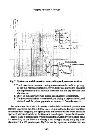
Fig.7. Upstream and downstream transit spool pressure vs time.
7. The downstream pressure reading was monitored to indicate passage
of the pig. After pig signal is received, flow was allowed to continue
for approximately 5-10 seconds to ensure that the pig travelled into
the receiver.
8. The 4-in exhaust valve was closed causing flow to terminate.
9. The 3-in control valves were closed, the piping is depressurized, and
drained, and the pig or pig train was removed from the receiver.
For most tests, the inlet chokes were sized and the initial tank pressure was
selected to achieve the desired flow rates, i.e. pig velocity. For very low flow
rates (less than 150gpm), the appropriate 3-in control valves were manually
operated with feedback from the flowmeter readings to control the flow rate.
Figs 6,7 and 8 demonstrate typical results for a water-driven pig test. Fig.6
is a recording of the flow rate during a test using a Knapp Polly Pig dual-
diameter (14x10) gauging pig. Fig.7 shows the upstream and downstream
395