
Page 126 - Pipeline Rules of Thumb Handbook
P. 126
Pipe Design 113
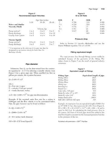
Figure 5 Figure 6
Recommended Liquid Velocities ID to OD Ratio
Pipe Size-Inches SDR F SDR F
3–10 10–28 28–48 7 0.706 13.5 0.852
Water and Similar 7.3 0.719 15.5 0.873
Viscosity Fluids 9 0.774 17 0.884
Velocity, fps 9.3 0.781 21 0.909
Pump suction* 1 to 4 3 to 6 5 to 8 11 0.817 26 0.928
Pump discharge 3 to 5 4 to 8 6 to 12 32.5 0.944
Gravity drain system 3 to 5 4 to 8 6 to 10
Pressure drop
Viscous liquids
Pump suction* 0.5 to 2 1 to 4 2 to 5
Refer to Section 13: Liquids—Hydraulics and use the
Pump discharge 3 to 5 4 to 6 5 to 7
Hazen-Williams equation. Use a C of 150.
* It is important in the selection of the pipe size that the
designated pump suction velocity be lower than the
discharge velocity. Fitting equivalent length
The exact pressure loss through fittings cannot readily be
calculated because of the geometry of the fitting. The
values shown in Figure 7 are the result of general industry
consensus.
Pipe diameter
Volumetric flow, Q, can be determined from the continu- Figure 7
ity equation Q = A ¥ V by selecting a suitable velocity from Equivalent Length of Fittings
Figure 5 for a given pipe size. When modified for flow in
gallons per minute, the equation becomes: Fitting Type Equivalent length of pipe
90deg.elbow 30D
Q = 2 449 ¥ V ¥ d 2 60deg.elbow 25D
.
45deg.elbow 16D
where 45deg.wye 60D
Q = flow rate in gpm Running tee 20D
V = velocity if feet per second Branch tee 50D
d = inside diameter, inches Gate valve, full open 8D
Butterfly valve (3≤ to 14≤) 40D
or d = ( Q ∏ 2 449 ¥ V) 12 for pipe size determination . Butterfly valve ≥14≤ 30D
.
Swing check valve 100D
Example: If the required water flow rate for a system is Ball valve full bore full open 3D
2,000gpm and the flow velocity is to be maintained below
8fps, the pipe diameter can be found as follows: Example: A running tee has an equivalent length of 20D. For
an 18≤ SDR 11 line, this represents 20 ¥ ID. From Figure 6,
d = ( Q ∏ 2 449 ¥ V) 12 ID = OD ¥ F = 18 ¥ 0.817 = 14.7≤¥ 20 = 294 ∏ 12 and is
.
equal to 24.5 feet. In calculating the total pressure drop in
12
.
d = (2000 2 449 ¥ ) 8 the system, 24.5 feet of 18 inch pipe should be added to the
∏
total line length to account for the increased pressure loss due
d = 10.1 inches inside diameter to the presence of the tee.
∏ (
OD ID F F from Figure ) 6 Published with permission—CSR TM PolyPipe
=