
Page 122 - Pipeline Rules of Thumb Handbook
P. 122
Pipe Design 109
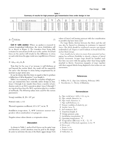
Table 1
Summary of results for high pressure gas transmission lines under design in Iran
values of lateral soil bearing pressure with due consideration
e B
d = ( Lin12 ) . (7)
2 to possible slip have been used.
For large blocks, friction between the block and the soil
Cell II—with anchor. Where an anchor is required to may also be figured in obtaining its resistance to imposed
contain longitudinal deflections, the stress distribution will forces. The block should be reinforced concrete cast against
be as shown in Figure 3. The transition from being fully undisturbed soil. Figures 4 and 5 indicate in broad detail the
restrained to unrestrained will occur at the anchor. Resultant anchor block design.
force on the anchor will simply be the difference in stress Care should also be taken to ensure that connected surface
on each side times the pipe metal area (equilibrium of forces) piping has sufficient flexibility to absorb a degree of lateral
or anchor movement. Scraper traps should be installed such
that they can move with the piping rather than being rigidly
F = (s LB -s LA ) A lb (8) attached to blocks. Numerous examples of traps together
m
with their support blocks being displaced a few inches are not
Note that for the case of an increase in wall thickness at
uncommon.
and beyond the anchor block, the result will be essentially
the same—the decrease in stress being compensated by an
increase in pipe metal area.
It can be shown that this force is equal to that to produce
a deflection of 2d in Equation 7 over length L. References
Table 1 is a summary of results for a number of high pres-
sure gas transmission lines currently under design in Iran. 1. Wilbur, W. E., Pipe Line Industry, February 1963.
2. Timoshenko, S., Theory of Elasticity.
Lines 1 through 4 are transfer lines from a number of pro-
duction units to an NGL separation plant. Lines 5 through 7
are injection lines from the NGL separation plant to a number
of wellheads. The following values were used for the various
Nomenclature
parameters:
A m Pipe metal area = p(D o = t)t, sq. in.
6
Young’s modulus, E, 29 ¥ 10 , psi
D o Pipe outside diameter, in.
D i Pipe inside diameter, in.
Poisson’s ratio, v, 0.3
t Pipe wall thickness, in.
E Young’s modulus of elasticity, psi
-6
Thermal expansion coefficient, 6.5 ¥ 10 , in./in.°F
F Anchor force, lb
F s Soil resistance, lb/ft
Installation temperature, T i , 80°F (minimum summer tem-
L Transition length, ft
perature when construction is in progress)
P Design pressure, psig
T i Installation temperature, °F
Negative stress values denote a compressive stress.
T o Operating temperature, °F
DT Temperature difference = (T o - T i ), °F
Discussion a Coefficient of thermal expansion, in./in.-°F
s Stress, psi
As shown in Table 1, anchor block forces can be quite large e Strain, in./in.
and therefore, careful attention must be paid to the design. v Poisson’s ratio
In order to minimize the size of the block, upper design limit d Deflection, in.