
Page 120 - Pipeline Rules of Thumb Handbook
P. 120
Pipe Design 107
1 2 ¥ 30 1 000 ∏, thickness = 30 000 inside diameter of the pipe in calculating this stress. This gives
¥
,
Wall thickness = 12inch . a slightly lower figure for the transverse tensile stress and
consequently gives less safety factor. The method used here
This method of calculating transverse tensile stress due to is based on the assumption that maximum stress occurs at
internal pressure on the pipe is the Barlow formula. Actually, outside diameter of the pipe. The results give a conservative
there are two accepted variations, and some designers use value for safety factor calculations.
How to calculate stress in above/below ground transition
Design of gas gathering/gas reinjection project in southern Iran provides solutions for deflection and
anchor block forces in long underground lines
P. J. Schnackenberg, Design Engineer, Iran-Texas Engineering Co., Tehran, Iran
Stresses and deflections occur in pipelines at the transition
from the below ground (fully restrained) to the above ground
(unrestrained) condition.
Analysis of the stresses and deflections in transition areas,
resulting from internal pressure/temperature change, is nec-
essary in determining anchor block requirements and design.
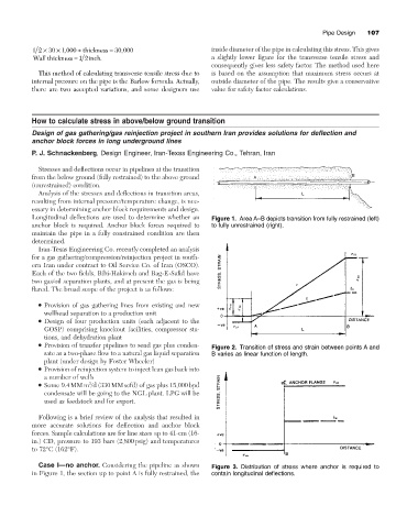
Longitudinal deflections are used to determine whether an Figure 1. Area A–B depicts transition from fully restrained (left)
anchor block is required. Anchor block forces required to to fully unrestrained (right).
maintain the pipe in a fully constrained condition are then
determined.
Iran-Texas Engineering Co. recently completed an analysis
for a gas gathering/compression/reinjection project in south-
ern Iran under contract to Oil Service Co. of Iran (OSCO).
Each of the two fields, Bibi-Hakimeh and Rag-E-Safid have
two gas/oil separation plants, and at present the gas is being
flared. The broad scope of the project is as follows:
• Provision of gas gathering lines from existing and new
wellhead separation to a production unit
• Design of four production units (each adjacent to the
GOSP) comprising knockout facilities, compressor sta-
tions, and dehydration plant
• Provision of transfer pipelines to send gas plus conden- Figure 2. Transition of stress and strain between points A and
sate as a two-phase flow to a natural gas liquid separation B varies as linear function of length.
plant (under design by Foster Wheeler)
• Provision of reinjection system to inject lean gas back into
a number of wells
3
• Some 9.4MMm /d (330MMscfd) of gas plus 15,000bpd
condensate will be going to the NGL plant. LPG will be
used as feedstock and for export.
Following is a brief review of the analysis that resulted in
more accurate solutions for deflection and anchor block
forces. Sample calculations are for line sizes up to 41-cm (16-
in.) CD, pressure to 193 bars (2,800psig) and temperatures
to 72°C (162°F).
Case I—no anchor. Considering the pipeline as shown Figure 3. Distribution of stress where anchor is required to
in Figure 1, the section up to point A is fully restrained, the contain longitudinal deflections.