
Page 118 - Pipeline Rules of Thumb Handbook
P. 118
Pipe Design 105
Weights of piping materials
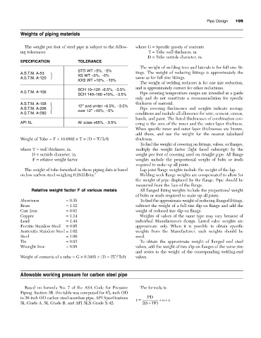
The weight per foot of steel pipe is subject to the follow- where G = Specific gravity of contents
ing tolerances: T = Tube wall thickness, in.
D = Tube outside diameter, in.
SPECIFICATION TOLERANCE
The weight of welding tees and laterals is for full size fit-
STD WT +5%, -5%
A.S.T.M. A-53 tings. The weight of reducing fittings is approximately the
A.S.T.M. A-120 XS WT +5%, -5% same as for full size fittings.
XXS WT +10%, -10%
The weight of welding reducers is for one size reduction,
and is approximately correct for other reductions.
SCH 10–120 +6.5%, -3.5%
A.S.T.M. A-106 Pipe covering temperature ranges are intended as a guide
SCH 140–160 +10%, -3.5%
only and do not constitute a recommendation for specific
A.S.T.M. A-158 12≤ and under +6.5%, -3.5% thickness of material.
A.S.T.M. A-206 over 12≤+10%, -5% Pipe covering thicknesses and weights indicate average
A.S.T.M. A-280 conditions and include all allowance for wire, cement, canvas,
bands, and paint. The listed thicknesses of combination cov-
API 5L All sizes +65%, -3.5% ering is the sum of the inner and the outer layer thickness.
When specific inner and outer layer thicknesses are known,
add them, and use the weight for the nearest tabulated
Weight of Tube = F ¥ 10.6802 ¥ T ¥ (D - T)lb/ft thickness.
To find the weight of covering on fittings, valves, or flanges,
where T = wall thickness, in. multiply the weight factor (light faced subscript) by the
D = outside diameter, in. weight per foot of covering used on straight pipe. All flange
F = relative weight factor weights include the proportional weight of bolts or studs
required to make up all joints.
The weight of tube furnished in these piping data is based Lap joint flange weights include the weight of the lap.
on low carbon steel weighing 0.2833lb/in. 3 Welding neck flange weights are compensated to allow for
the weight of pipe displaced by the flange. Pipe should be
measured from the face of the flange.
Relative weight factor F of various metals All flanged fitting weights include the proportional weight
of bolts or studs required to make up all joints.
Aluminum = 0.35 To find the approximate weight of reducing-flanged fittings,
Brass = 1.12 subtract the weight of a full size slip-on flange and add the
Cast Iron = 0.91 weight of reduced size slip-on flange.
Copper = 1.14 Weights of valves of the same type may vary because of
Lead = 1.44 individual Manufacturer’s design. Listed valve weights are
Ferritic Stainless Steel = 0.95 approximate only. When it is possible to obtain specific
Austenitic Stainless Steel = 1.02 weights from the Manufacturer, such weights should be
Steel = 1.00 used.
Tin = 0.93 To obtain the approximate weight of flanged end steel
Wrought Iron = 0.98 valves, add the weight of two slip-on flanges of the same size
and series to the weight of the corresponding welding-end
2
Weight of contents of a tube = G ¥ 0.3405 ¥ (D - 2T) lb/ft valves.
Allowable working pressure for carbon steel pipe
Based on formula No. 7 of the ASA Code for Pressure The formula is:
5
Piping, Section 3B, this table was computed for 6 / 8 -inch OD
to 36-inch OD carbon steel seamless pipe, API Specifications PD
uc
t = ++
5L Grade A, 5L Grade B, and API 5LX Grade X-42. ( 2 SYP)
+