
Page 246 - Pipeline Rules of Thumb Handbook
P. 246
Corrosion/Coatings 233
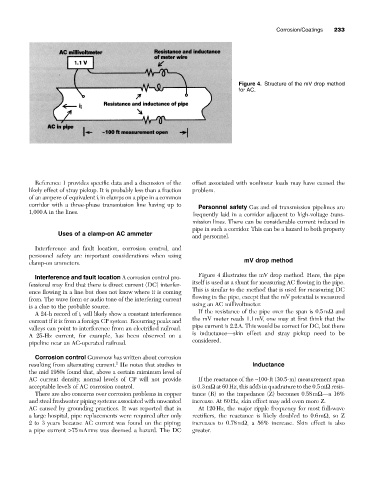
Figure 4. Structure of the mV drop method
for AC.
Reference 1 provides specific data and a discussion of the offset associated with nonlinear loads may have caused the
likely effect of stray pickup. It is probably less than a fraction problem.
of an ampere of equivalent i i in clamps on a pipe in a common
corridor with a three-phase transmission line having up to
Personnel safety Gas and oil transmission pipelines are
1,000A in the lines.
frequently laid in a corridor adjacent to high-voltage trans-
mission lines. There can be considerable current induced in
pipe in such a corridor. This can be a hazard to both property
Uses of a clamp-on AC ammeter
and personnel.
Interference and fault location, corrosion control, and
personnel safety are important considerations when using
mV drop method
clamp-on ammeters.
Figure 4 illustrates the mV drop method. Here, the pipe
Interference and fault location A corrosion control pro-
itself is used as a shunt for measuring AC flowing in the pipe.
fessional may find that there is direct current (DC) interfer-
This is similar to the method that is used for measuring DC
ence flowing in a line but does not know where it is coming
flowing in the pipe, except that the mV potential is measured
from. The wave form or audio tone of the interfering current
using an AC millivoltmeter.
is a clue to the probable source.
If the resistance of the pipe over the span is 0.5mW and
A 24-h record of i i will likely show a constant interference
the mV meter reads 1.1mV, one may at first think that the
current if it is from a foreign CP system. Recurring peaks and
pipe current is 2.2A. This would be correct for DC, but there
valleys can point to interference from an electrified railroad.
is inductance—skin effect and stray pickup need to be
A 25-Hz current, for example, has been observed on a
considered.
pipeline near an AC-operated railroad.
Corrosion control Gummow has written about corrosion
2
resulting from alternating current. He notes that studies in Inductance
the mid 1980s found that, above a certain miminum level of
AC current density, normal levels of CP will not provide If the reactance of the ~100-ft (30.5-m) measurement span
acceptable levels of AC corrosion control. is 0.3mW at 60Hz, this adds in quadrature to the 0.5mW resis-
There are also concerns over corrosion problems in copper tance (R) so the impedance (Z) becomes 0.58mW—a 16%
and steel freshwater piping systems associated with unwanted increase. At 60Hz, skin effect may add even more Z.
AC caused by grounding practices. It was reported that in At 120Hz, the major ripple frequency for most full-wave
a large hospital, pipe replacements were required after only rectifiers, the reactance is likely doubled to 0.6mW, so Z
2 to 3 years because AC current was found on the piping; increases to 0.78mW, a 56% increase. Skin effect is also
a pipe current >75mArms was deemed a hazard. The DC greater.