
Page 292 - Pipeline Rules of Thumb Handbook
P. 292
Gas—Compression 279
Determine the inlet flow volume, Q 1 : r p = P P = 100 30 = 3 33
.
2
1
Determine the approximate discharge temperature, T 2 .
1 ( [
Q 1 = m Z RT 1 ) ( 144 P 1 )]
1
nn -=[ k k - ] 1 n p
1
.
.
where m = mass flow =[1 126 (1 126. -1 000 )](0 77. )
Z 1 = inlet compressibility factor = 688
.
R = gas constant = 1,545/MW
T 1 = inlet temperature °R T 2 = T r p1 () ( n 1) n
-
P 1 = inlet pressure
.
= ( 60 460 3 33) 16 88
+
)( .
= 619∞ R 159= ∞ F
)(
)(
5 000 0 955 1 545 60 460) ( .
Q 1 = , ( [ . )( , )( + 45 5 144 30)]
,
= 19 517 ICFM where T 1 = inlet temp
Determine the average compressibility, Z a .
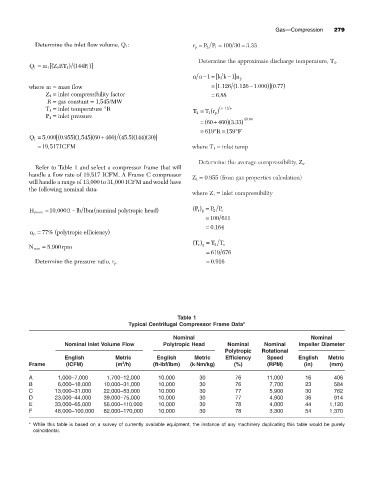
Refer to Table 1 and select a compressor frame that will
handle a flow rate of 19,517 ICFM. A Frame C compressor
Z 1 = 0.955 (from gas properties calculation)
will handle a range of 13,000 to 31,000 ICFM and would have
the following nominal data:
where Z 1 = inlet compressibility
H pnom = 10 000 ft lb lbm(nominal polytropic head ) P r () = P P c
-
,
2
2
= 100 611
= 0 164.
(
n p = 77% polytropic efficiency )
T r () = T T c
2
N nom = 5,900rpm 2
= 619 676
Determine the pressure ratio, r p . = 0 916.
Table 1
Typical Centrifugal Compressor Frame Data*
Nominal Nominal
Nominal Inlet Volume Flow Polytropic Head Nominal Nominal Impeller Diameter
Polytropic Rotational
English Metric English Metric Efficiency Speed English Metric
3
Frame (ICFM) (m /h) (ft-lbf/lbm) (k◊Nm/kg) (%) (RPM) (in) (mm)
A 1,000–7,000 1,700–12,000 10,000 30 76 11,000 16 406
B 6,000–18,000 10,000–31,000 10,000 30 76 7,700 23 584
C 13,000–31,000 22,000–53,000 10,000 30 77 5,900 30 762
D 23,000–44,000 39,000–75,000 10,000 30 77 4,900 36 914
E 33,000–65,000 56,000–110,000 10,000 30 78 4,000 44 1,120
F 48,000–100,000 82,000–170,000 10,000 30 78 3,300 54 1,370
* While this table is based on a survey of currently available equipment, the instance of any machinery duplicating this table would be purely
coincidental.