
Page 287 - Pipeline Rules of Thumb Handbook
P. 287
274 Pipeline Rules of Thumb Handbook
Compression horsepower determination
The method outlined below permits determination of 5. Figure 3 gives horsepower requirements for compres-
approximate horsepower requirements for compression of sion of one million cuft per day for the compression
gas. ratios and N values commonly encountered in oil pro-
ducing operations.
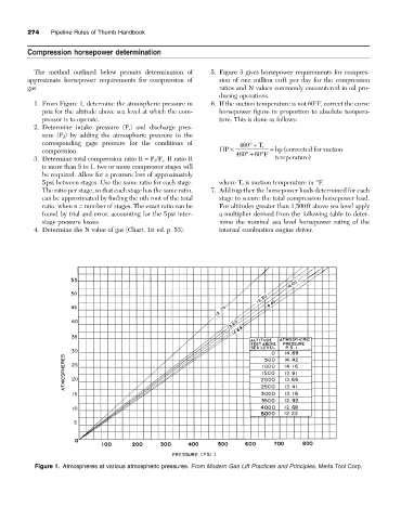
1. From Figure 1, determine the atmospheric pressure in 6. If the suction temperature is not 60°F, correct the curve
psia for the altitude above sea level at which the com- horsepower figure in proportion to absolute tempera-
pressor is to operate. ture. This is done as follows:
2. Determine intake pressure (P s ) and discharge pres-
sure (P d ) by adding the atmospheric pressure to the
corresponding gage pressure for the conditions of 460 ∞+ T s
compression. HP ¥ 460 ∞+ 60 ∞ F = hp ( corrected for suction
3. Determine total compression ratio R = P d /P s . If ratio R temperature)
is more than 5 to 1, two or more compressor stages will
be required. Allow for a pressure loss of approximately
5psi between stages. Use the same ratio for each stage. where T s is suction temperature in °F.
The ratio per stage, so that each stage has the same ratio, 7. Add together the horsepower loads determined for each
can be approximated by finding the nth root of the total stage to secure the total compression horsepower load.
ratio, when n = number of stages. The exact ratio can be For altitudes greater than 1,500ft above sea level apply
found by trial and error, accounting for the 5psi inter- a multiplier derived from the following table to deter-
stage pressure losses. mine the nominal sea level horsepower rating of the
4. Determine the N value of gas (Chart, 1st ed. p. 53). internal combustion engine driver.
Figure 1. Atmospheres at various atmospheric pressures. From Modern Gas Lift Practices and Principles, Merla Tool Corp.