
Page 285 - Pipeline Rules of Thumb Handbook
P. 285
272 Pipeline Rules of Thumb Handbook
where P r = Reduced pressure Calculate suction capacity.
P c = Critical pressure = 1,071psia for CO 2
P = Suction pressure Q 1 = E v ¥ P d
= 0.93 ¥ 107.6
From the generalized compressibility chart (page 231): = 100.1cfm
Z 1 = 0.312 Calculate piston speed.
Determine discharge compressibility. Calculate discharge PS =[2 ¥ S t ¥ N] 12
temperature by using Equation 9. =[2 12 ¥ 300 12
]
¥
= 600 ft min
r p = 3 440 1 720
,
,
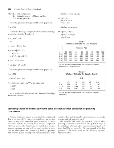
= 2 Table 1
Efficiency Multiplier for Low Pressure
k = cp cv = 13 for CO 2
.
Pressure Psia
- )
.
T 2 = 575 ¥[ 2 0 ( . 13 1 1 3 . ]
10 14.7 20 40 60 80 100 150
r p
.
= 674 7∞ R
3.0 .990 1.00 1.00 1.00 1.00 1.00 1.00 1.00
.
-
= 674 7 460 = 214∞ F 2.5 .980 .985 .990 .995 1.00 1.00 1.00 1.00
2.0 .960 .965 .970 .980 .990 1.00 1.00 1.00
.
T r = 674 7 548 1 23 1.5 .890 .900 .920 .940 .960 .980 .990 1.00
.
=
,
,
P r = 3 440 1 071 3 21 Source: Modified courtesy of the Gas Processors Suppliers
.
=
Association and Ingersoll-Rand.
From the generalized compressibility chart (page 231):
Table 2
Z 2 = 0.575 Efficiency Multiplier for Specific Gravity
.
f = 0 575 1 61 1 843 SG
.
.
=
1.5 1.3 1.0 0.8 0.6
.
r p
11 3
1
-
.
E v = 097 - ( [ 1 1843 ) ¥ 20. - ] ¥ 0 12 005
.
.
.
2.0 0.99 1.0 1.0 1.0 1.01
= 0 929 1.75 0.97 0.99 1.0 1.01 1.02
.
= 93% 1.5 0.94 0.97 1.0 1.02 1.04
Note: A value of 0.05 was used for L because of the high Source: Modified courtesy of the Gas Processors Suppliers
differential pressure. Association.
Estimating suction and discharge volume bottle sizes for pulsation control for reciprocating
compressors
Pressure surges are created as a result of the cessation of complex when multiple cylinders are connected to one header
flow at the end of the compressor’s discharge and suction or when multiple stages are used.
stroke. As long as the compressor speed is constant, the pres- API Standard 618 should be reviewed in detail when
sure pulses will also be constant. A low pressure compressor planning a compressor installation. The pulsation level at
will likely require little if any treatment for pulsation control; the outlet side of any pulsation control device, regardless of
however, the same machine with increased gas density, pres- type, should be no more than 2% peak-to-peak of the line
sure, or other operational changes may develop a problem pressure of the value given by the following equation,
with pressure pulses. Dealing with pulsation becomes more whichever is less.