
Page 284 - Pipeline Rules of Thumb Handbook
P. 284
Gas—Compression 271
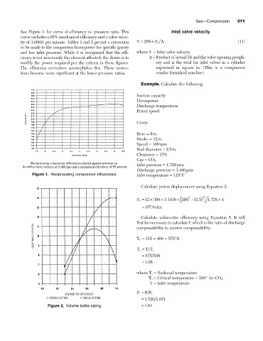
See Figure 1: for curve of efficiency vs. pressure ratio. This Inlet valve velocity
curve includes a 95% mechanical efficiency and a valve veloc-
ity of 3,000ft per minute. Tables 1 and 2 permit a correction V = 288 ¥ P A (11)
d
to be made to the compressor horsepower for specific gravity
and low inlet pressure. While it is recognized that the effi- where V = Inlet valve velocity
ciency is not necessarily the element affected, the desire is to A = Product of actual lift and the valve opening periph-
modify the power required per the criteria in these figures. ery and is the total for inlet valves in a cylinder
The efficiency correction accomplishes this. These correc- expressed in square in. (This is a compressor
tions become more significant at the lower pressure ratios. vendor furnished number.)
Example. Calculate the following:
Suction capacity
Horsepower
Discharge temperature
Piston speed
Given:
Bore = 6in.
Stroke = 12in.
Speed = 300rpm
Rod diameter = 2.5in.
Clearance = 12%
Gas = CO 2
Inlet pressure = 1,720psia
Discharge pressure = 3,440psia
Figure 1. Reciprocating compressor efficiencies. Inlet temperature = 115°F
Calculate piston displacement using Equation 2.
2 2
[ 2 6
.
.
P d = 12 ¥ 300 ¥ 3 1416 ¥ () -(2 5 ) ] 1 728, ¥ 4
= 107 6 cfm
.
Calculate volumetric efficiency using Equation 5. It will
first be necessary to calculate f, which is the ratio of discharge
SIZE MULTIPLIER T 1 = 115 + 460 = 575°R
compressibility to suction compressibility.
T r = T T c
= 575 548
= 105
.
where T r = Reduced temperature
T c = Critical temperature = 548° for CO 2
T = Inlet temperature
P r =
VOLUMETRIC EFFICIENCY P P c
D DOUBLE ACTING X SINGLE ACTING = 1 720 1 071
,
,
.
Figure 2. Volume bottle sizing. = 161