
Page 118 - Pipelines and Risers
P. 118
Hydrodynamics around Pipes 91
The total velocity is obtained by adding the velocities from waves and currents together:
v = v,,, -+ v,,,~ (of a water particle) (6.26)
6.5 Hydrodynamic Forces
6.5.1 Hydrodynamic Drag and Inertia Forces
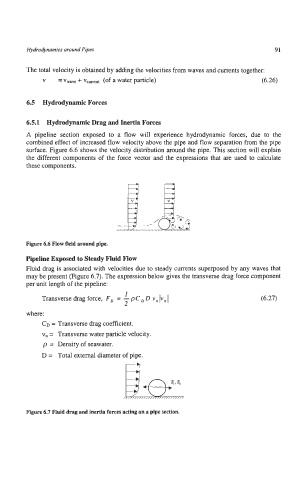
A pipeline section exposed to a flow will experience hydrodynamic forces, due to the
combined effect of increased flow velocity above the pipe and flow separation from the pipe
surface. Figure 6.6 shows the velocity distribution around the pipe. This section will explain
the different components of the force vector and the expressions that are used to calculate
these components.
Figure 6.6 Flow field around pipe.
Pipeline Exposed to Steady Fluid Flow
Fluid drag is associated with velocities due to steady currents superposed by any waves that
may be present (Figure 6.7). The expression below gives the transverse drag force component
per unit length of the pipeline:
Transverse drag force, F, = - pC, D vn Iv, I (6.27)
I
2
where:
CD = Transverse drag coefficient.
vn = Transverse water particle velocity.
p = Density of seawater.
a
D = Total external diameter of pipe.
Figure 6.7 Fluid drag and inertia forces acting on a pipe section.