
Page 143 - Pipelines and Risers
P. 143
116 Chapter 8
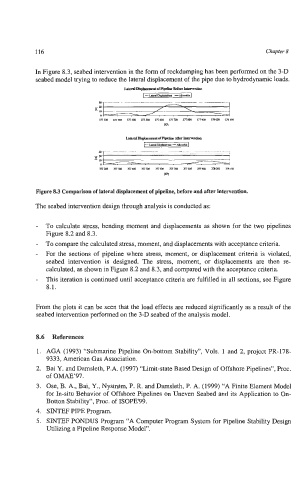
In Figure 8.3, seabed intervention in the form of rockdumping has been performed on the 3-D
seabed model trying to reduce the lateral displacement of the pipe due to hydrodynamic loads.
JArml~orPlkrLlrt~
-,U!&kl
I--U.nl!%wmm -
a ___.__-__I_____
-m / \
- 10
0 /,
mw anm mua mxo mun mw 371105 mm maa mica
W
Figure 8.3 Comparison of lateral displacement of pipeline, before and after intervention.
The seabed intervention design through analysis is conducted as:
- To calculate stress, bending moment and displacements as shown for the two pipelines
Figure 8.2 and 8.3.
- To compare the calculated stress, moment, and displacements with acceptance criteria.
- For the sections of pipeline where stress, moment, or displacement criteria is violated,
seabed intervention is designed. The stress, moment, or displacements are then re-
calculated, as shown in Figure 8.2 and 8.3, and compared with the acceptance criteria.
- This iteration is continued until acceptance criteria are fulfilled in all sections, see Figure
8.1.
From the plots it can be seen that the load effects are reduced significantly as a result of the
seabed intervention performed on the 3-D seabed of the analysis model.
8.6 References
1. AGA (1993) “Submarine Pipeline On-bottom Stability”, Vols. 1 and 2, project PR-178-
9333, American Gas Association.
2. Bai Y. and Damsleth, P.A. (1997) “Limit-state Based Design of Offshore Pipelines”, Proc.
of OMAE‘97.
3. Ose, B. A., Bai, Y., Nystrom, P. R. and Damsleth, P. A. (1999) “A Finite Element Model
for In-situ Behavior of Offshore Pipelines on Uneven Seabed and its Application to On-
Botton Stability“, Proc. of ISOPE99.
4. SINTJ3F PIPE Program.
5. SINTEF PONDUS Program “A Computer Program System for Pipeline Stability Design
Utilizing a Pipeline Response Model”.