
Page 289 - Pipelines and Risers
P. 289
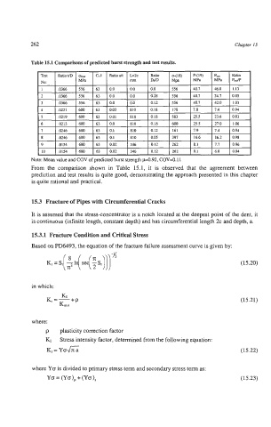
262                                                              Chapter 15


              Test   RatiotiD   crm   GI   Ratioalt   L2c   Ratio   0-118)   P-(19)   Pet   Ratio
              No:         MPa             nun    DdD    Mpa    MPa   MPa   P,Jp
              1     .0366   556   63   0.0   0.0   0.0   556   40.7   46.0   1.13
              2     .0366   556   63   0.0   0.0   0.28   556   40.7   34.7   0.85
              3     ,0366   556   63   0.0   0.0   0.12   556   40.7   42.0   1.03
              4     .0221   600   63   0.03   810   0.18   178   7.8   7.4   0.94
              5     .0219   600   63   0.01   810   0.18   583   25.5   23.6   0.83
              6     .0213   600   63   0.0   810   0.18   600   25.5   27.0   1.06


           Note: Mean value and COV of predicted burst strength pO.92, COV=O.I 1
           From  the  comparison shown  in  Table  15.1,  it  is  observed  that  the  agreement  between
           prediction and test results is quite good, demonstrating the approach presented in this chapter
           is quite rational and practical.


           15.3  Fracture of Pipes with Circumferential Cracks

           It is assumed that the stressconcentrator is a notch located at the deepest point of the dent, it
           is continuous (infinite length, constant depth) and has circumferential length 2c and depth, a.

           15.3.1  Fracture Condition and Critical Stress
           Based on PD6493, the equation of the fracture failure assessment curve is given by:


                                                                              (15.20)


           in which:

                                                                              (15.21)


           where:
                p   plasticity correction factor
                KI  Stress intensity factor, determined from the following equation:
                KI = Yo&                                                      (15.22)

           where Yo is divided to primary stress term and secondary stress term as:
                Yo = (Yo), + (Yo),                                            (15.23)