
Page 448 - Pipelines and Risers
P. 448
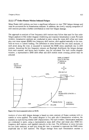
Fatigue of Risers                                                     415


         22.2.2  2"d Order Floater Motion Induced Fatigue
         Mean floater drift motions can have a significant influence on riser TOP fatigue damage and
         must be accounted for in linearisation analyses. In addition, the slowly varying component of
         drift motions provides a further contribution to total riser fatigue damage.

         The approach to analysis of low frequency drift motions may follow that used for first order
         fatigue analysis in that scatter diagram windowing and response linearisation is used. For each
         window, linearisation analyses are conducted in pairs, using the mean drift offset and mean
         plus root mean square (RMS) low frequency drift motion, each applied statically to the riser,
         with no wave or current loading. The difference in stress between the two static analyses, at
         each point  along  the riser,  is  assumed to represent  the RMS  stress amplitude due  to drift
         motions. Assuming the low frequency stresses are Rayleigh distributed, the fatigue damage
         from each seastate,  and hence each  window, may  be calculated.  For each  scatter diagram
         window, a representative  EMS  drift offset and drift motion  mean  crossing period must be
         selected.
                                                         DISPLACEMENT
                                                         DUE TO WAVES
                                                         1 st ORDER &
                                                         2"d ORDER
              FLOW-
              VELOCITY
              1 st ORDER
                                                          FF'S  OR TLP
                                             MWL


                      b

                      t


         Analysis of  slow drift fatigue damage is based on static analysis of  floater motions with no
         current or wave applied. The scatter diagram is first split into 6 linearisation windows, the
         seastates in each having similar drift characteristics. For each window, linearisation analyses
         are conducted  in  pairs,  using  a  representative mean  drift  offset  and  mean  plus  RMS  low
         frequency drift motion, each applied statically to the riser. The difference in stress between
         the two static analyses, at each pint along the riser, is assumed to represent the RMS stress
         amplitude  due  to  drift  motions.  The  fatigue  damage  from  each  linearisation  seastate  is