
Page 241 - Planning and Design of Airports
P. 241
Geometric Design of the Airfield 205
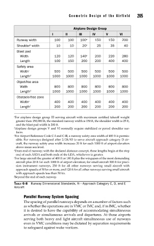
Airplane Design Group
I II III IV V VI
Runway width 100 100 100 a 150 150 200
b
Shoulder width 10 10 20 a 25 35 40
Blast pad
Width 120 120 140 a 200 220 280
Length 100 150 200 200 400 400
Safety area
Width c 500 500 500 500 500 500
Length d 1000 1000 1000 1000 1000 1000
Object-free area
Width 800 800 800 800 800 800
Length d 1000 1000 1000 1000 1000 1000
Obstacle-free zone
Width e 400 400 400 400 400 400
Length f 200 200 200 200 200 200
a For airplane design group III serving aircraft with maximum certified takeoff weight
greater than 150,000 lb, the standard runway width is 150 ft, the shoulder width is 25 ft,
and the blast pad width is 200 ft.
b Airplane design groups V and VI normally require stabilized or paved shoulder sur-
faces.
c For Airport Reference Code C-I and C-II, a runway safety area width of 400 ft is permis-
sible. For runways designed after 2/28/83 to serve aircraft approach category D air-
craft, the runway safety area width increases 20 ft for each 1000 ft of airport elevation
above mean sea level.
d From end of runway; with the declared distance concept, these lengths begin at the stop
end of each ASDA and both ends of the LDA, whichever is greater.
e For large aircraft the greater of 400 ft or 180 ft plus the wingspan of the most demanding
aircraft plus 20 ft for each 1000 ft of airport elevation; for small aircraft 300 ft for preci-
sion instrument runways, 250 ft for all other runways serving small aircraft with
approach speeds of 50 kn or more, and 120 ft for all other runways serving small aircraft
with approach speeds less than 50 kn.
f Beyond the end of each runway.
TABLE 6-8 Runway Dimensional Standards, ft—Approach Category C, D, and E
Aircraft
Parallel Runway System Spacing
The spacing of parallel runways depends on a number of factors such
as whether the operations are in VMC or IMC and, if in IMC, whether
it is desired to have the capability of accommodating simultaneous
arrivals or simultaneous arrivals and departures. At those airports
serving both heavy and light aircraft simultaneous use of runways
even in VMC conditions may be dictated by separation requirements
to safeguard against wake vortices.