
Page 245 - Planning and Design of Airports
P. 245
Geometric Design of the Airfield 209
Aircraft Approach Category
A B C D E
Gradient (%)
Pavement longitudinal a
Maximum 2.0 2.0 1.5 b 1.5 b 1.5 b
Maximum change 2.0 2.0 1.5 1.5 1.5
Pavement transverse
Maximum 2.0 2.0 1.5 1.5 1.5
Shoulder transverse
Minimum 3.0 3.0 1.5 c 1.5 c 1.5 c
Maximum d 5.0 5.0 5.0 5.0 5.0
Runway end safety area
Maximum longitudinal e 3.0 3.0 3.0 3.0 3.0
Maximum longitudinal
Grade change 2.0 2.0 2.0 2.0 2.0
Minimum transverse 1.5 1.5 1.5 1.5 1.5
Maximum transverse d 5.0 5.0 3.0 3.0 3.0
Vertical curve (ft)
Minimum length a,f 300 g 300 g 1000 1000 1000
Minimum distance between 250 250 1000 1000 1000
points of intersection a,h
a Applies also to runway safety area adjacent to sides of the runway.
b May not exceed 0.8 percent in the first and last quarter of runway.
c A minimum of 3 percent for turf.
d A slope of 5 percent is recommended for a 10 ft width adjacent to the pavement areas to
promote drainage.
e For the first 200 ft from the end of the runway and if it slopes it must be downward. For
the remainder of the runway safety area the slope must be such that any upward slope
does not penetrate the approach surface or clearway plane and any downward slope
does not exceed 5 percent.
f For each 1 percent change in grade.
g No vertical curve is required if the grade change is less than 0.4 percent.
h Distance is multiplied by the sum of the absolute grade grade changes in percent.
Source: Federal Aviation Administration [6].
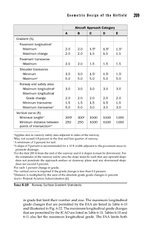
TABLE 6-10 Runway Surface Gradient Standards
in grade but limit their number and size. The maximum longitudinal
grade changes that are permitted by the FAA are listed in Table 6-10
and illustrated in Fig. 6-22. The maximum longitudinal grade changes
that are permitted by the ICAO are listed in Table 6-11. Tables 6-10 and
6-11 also list the maximum longitudinal grade. The FAA limits both