
Page 236 - Planning and Design of Airports
P. 236
Geometric Design of the Airfield 201
NOTES:
• CFM56–7827 ENGINES RATED AT 27,300 LB SLST
• NO ENGINE AIR BLEED FOR AIR CONDITIONING
• ZERO WIND, ZERO RUNWAY GRADIENT
• DRY RUNWAY SURFACE
• CONSULT WITH USING AIRLINE FOR SPECIFIC
OPERATING PROCEDURE PRIOR TO FACILITY DESIGN
• LINEAR INTERPOLATION BETWEEN ALTITUDES INVALID
• LINEAR INTERPOLATION BETWEEN TEMPERATURES INVALID
15
4.5
14 STANDARD DAY + 27°F
(STD + 15°C) TIRE SPEED LIMIT
4.0 13
F.A.R. TAKEOFF RUNWAY LENGTH (1,000 METERS) 3.0 1,000 FEET 11 9 8 7 AIRPORT ELEVATION FLAPS 5
12
3.5
10
FLAPS 15
FEET (METERS)
8,000 (2,438)
2.5
6,000 (1,829)
2.0
2,000 (610)
SEA LEVEL
1.5 6 5 4,000 (1,219) FLAPS 25
4
MAX DESIGN TAKEOFF WT
1.0 174,200 LB (79,016 KG)
3
120 125 130 135 140 145 150 155 160 165 170 175
1,000 POUNDS
55 60 65 70 75 80
(1,000 KILOGRAMS)
OPERATIONAL TAKEOFF WEIGHT
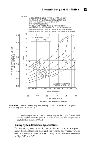
FIGURE 6-18 Takeoff runway length for Boeing 737–900 (CFM56-7B27 Engines)
(Ref: Boeing Doc. D6-58325-3).
For design purposes, the design runway length is the longer of the required
runway lengths for landing and for takeoff. In this case, the design runway
length for this example is 9000 ft.
Runway System Geometric Specifications
The runway system at an airport consists of the structural pave-
ment, the shoulders, the blast pad, the runway safety area, various
obstruction-free surfaces, and the runway protection zone, as shown
in Figs. 6-19 and 6-20.