
Page 235 - Planning and Design of Airports
P. 235
200 Airp o r t D e sign
NOTES:
• STANDARD DAY
• AUTO SPOILERS OPERATIVE
• ANTI-SKID OPERATIVE
• ZERO WIND
• CONSULT USING AIRLINE FOR SPECIFIC
OPERATING PROCEDURE PRIOR TO FACILITY DESIGN
9
FLAPS 40 DRY RUNWAY
WET RUNWAY
2.5
8
AIRPORT ELEVATION
FEET (METERS)
F.A.R. LANDING RUNWAY LENGTH (1,000 METERS) 2.0 1,000 FEET 6 2,000 (610)
8,000 (2,438)
6,000 (1,829)
7
4,000 (1,219)
SEA LEVEL
5
1.5
4
1.0 MAX DESIGN LANDING WT
146,300 (66,360 KG)
3
100 110 120 130 140 150
1,000 POUNDS
50 55 60 65
(1,000 KILOGRAMS)
OPERATIONAL LANDING WEIGHT
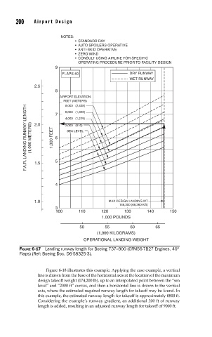
FIGURE 6-17 Landing runway length for Boeing 737–900 (CFM56-7B27 Engines, 40°
Flaps) (Ref: Boeing Doc. D6-58325-3).
Figure 6-18 illustrates this example. Applying the case example, a vertical
line is drawn from the base of the horizontal axis at the location of the maximum
design takeoff weight (174,200 lb), up to an interpolated point between the “sea
level” and “2000 ft” curves, and then a horizontal line is drawn to the vertical
axis, where the estimated required runway length for takeoff may be found. In
this example, the estimated runway length for takeoff is approximately 8800 ft.
Considering the example’s runway gradient, an additional 200 ft of runway
length is added, resulting in an adjusted runway length for takeoff of 9000 ft.