
Page 276 - Planning and Design of Airports
P. 276
Geometric Design of the Airfield 237
Taxiing Speed Radius of Exit curve
mph kph Feet Meters
10 16 50 15
20 32 200 60
30 48 450 135
40 64 800 240
50 80 1,250 375
60 96 1,800 540
Source: International Civil Aviation Organization [4].
TABLE 6-22 Radii of Curvature for Transport Category Aircraft
of curvature for the taxiway centerline of 275 m (900 ft) for aerodrome
code number 1 and 2 runways and 550 m (1800 ft) for aerodrome code
number 3 and 4 runways. This will allow exit speeds under wet con-
ditions of 65 km/h (40 mi/h) for aerodrome code number 1 and 2
runways and 93 km/h (60 mi/h) for aerodrome code number 3 and 4
runways. It also recommends a straight tangent section after the turn-
off curve to allow exiting aircraft to come to a full stop clear of the
intersecting taxiway when the intersection is 30°. This tangent dis-
tance should be 35 m (115 ft) for aerodrome code number 1 and 2
runways and 75 m (250 ft) for aerodrome code number 3 and 4 run-
ways [2, 4].
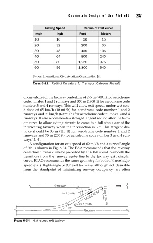
A configuration for an exit speed of 60 mi/h and a turnoff angle
of 30° is shown in Fig. 6-34. The FAA recommends that the taxiway
centerline circular curve be preceded by a 1400-ft spiral to smooth the
transition from the runway centerline to the taxiway exit circular
curve. ICAO recommends the same geometry for both of these high-
speed exits. Right-angle or 90° exit taxiways, although not desirable
from the standpoint of minimizing runway occupancy, are often
C L TAXIWAY
TRAFFIC FLOW 800' R (250 M)
25' R (7.5 M)
25' R (7.5 M)
30°
C L RUNWAY
FIGURE 6-34 High-speed exit taxiway.