
Page 328 - Planning and Design of Airports
P. 328
286 Airp o r t D e sign
There are several other complexities associated with pavement
overlays, particularly with respect to rigid pavements, that are
beyond the scope of this text. It is strongly recommended that further
study include in-depth review of the FAA Advisory Circular AC
150/5320-6E, “Airfield Pavement Design and Evaluation,” as well as
familiarization with the FAARFIELD software package.
Pavements for Light Aircraft
Pavements for light aircraft are defined as landing areas intended
for personal or other small aircraft engaged in nonscheduled activi-
ties, such as recreational, agricultural, or instructional activities, or
small aircraft charter operations. Pavements for light aircraft are
designed to accommodate aircraft with less than 30,000 lb maxi-
mum gross weight. In many cases these aircraft will not exceed
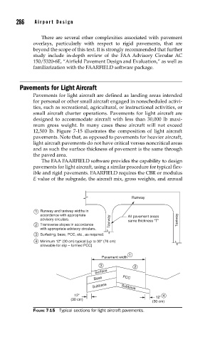
12,500 lb. Figure 7-15 illustrates the composition of light aircraft
pavements. Note that, as opposed to pavements for heavier aircraft,
light aircraft pavements do not have critical versus noncritical areas
and as such the surface thickness of pavement is the same through
the paved area.
The FAA FAARFIELD software provides the capability to design
pavements for light aircraft, using a similar procedure for typical flex-
ible and rigid pavements. FAARFIELD requires the CBR or modulus
E value of the subgrade, the aircraft mix, gross weights, and annual
Runway
1 Runway and taxiway widths in
accordance with appropriate All pavement areas
advisory circulars. Taxiway same thickness “T” Taxiway
2 Transverse slopes in accordance
with appropriate advisory circulars.
3 Surfacing, base, PCC, etc., as required.
4 Minimum 12" (30 cm) typical [up to 30" (76 cm)
allowable for slip – formed PCC]
1
Pavement width
3 2
Surface
Base PCC
Subbase Subbase
12" 12" 4
(30 cm)
(30 cm)
FIGURE 7-15 Typical sections for light aircraft pavements.