
Page 337 - Planning and Design of Airports
P. 337
Airport Lighting, Marking, and Signage 295
β
Horizontal
α Fuselage
axis
h
Glide slope VR Visual cone
φ θ α − β
Runway H
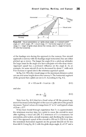
FIGURE 8-2 Visual parameters: ϕ = glide slope angle, α = cockpit cutoff
angle, β = pitch angle, VR = visual range, H = horizontal segment of visual
range, h = height of glide slope above the runway, and θ = angle formed by
VR with the horizontal.
of the fuselage axis during the approach to the runway. Few aircraft
approach a runway with the fuselage angle horizontal; they are either
pitched up or down. The larger the angle β (in a pitch-up attitude),
the larger must be the angle α to have adequate over-the-nose vision.
Approach speed has a profound influence on the angle β. As an
example, for some aircraft β can be decreased by about 1° with each
5 kn increase in speed above the reference approach speed.
In Fig. 8-2, VR is the visual range or the maximum distance a pilot
can see and some height above the runway h. The horizontal segment
of the ground that a pilot can see is H. According to Fig. 8-2,
H = VR cos Θ − h cot (α − β) (8-1)
and also
h
sin Θ= (8-2)
VR
Note from Eq. (8-1) that for a fixed value of VR the ground seg-
ment H increases as the height h of the eyes of a pilot above the ground
decreases. Typical values of α range from 11° to 16° and typical values
of β are ± 0.5°.
It has been found through experience that 3 s is approximately
the minimum reaction time for a pilot to cause the aircraft to react
after sighting a visual aid [28]. If a minimum of 3 s is necessary for
perception, pilot action, aircraft response, and checking the response,
and if the approach speed of the aircraft is 150 mi/h (220 ft/s), then
the minimum horizontal segment on the ground should not be less
than 660 ft. Using Eq. (8-1) with the glide slope angle, ϕ, of 2.5° and a