
Page 336 - Planning and Design of Airports
P. 336
294 Airp o r t D e sign
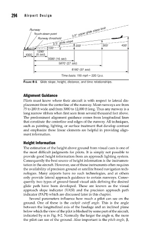
3.0° upper glide slope limit
Runway
Touch-down point
Runway threshold
2.5° glide slope
200' 300' 400'
100'
1290'
1000' (6 sec)
3580' (16 sec)
5870' (27 sec)
8160' (37 sec)
Time basis: 150 mph = 220 f.p.s.
FIGURE 8-1 Glide slope, height, distance, and time relationships.
Alignment Guidance
Pilots must know where their aircraft is with respect to lateral dis-
placement from the centerline of the runway. Most runways are from
75 to 200 ft wide and from 3000 to 12,000 ft long. Thus any runway is a
long narrow ribbon when first seen from several thousand feet above.
The predominant alignment guidance comes from longitudinal lines
that constitute the centerline and edges of the runway. All techniques,
such as painting, lighting, or surface treatment that develop contrast
and emphasize these linear elements are helpful in providing align-
ment information.
Height Information
The estimation of the height above ground from visual cues is one of
the most difficult judgments for pilots. It is simply not possible to
provide good height information from an approach lighting system.
Consequently the best source of height information is the instrumen-
tation in the aircraft. However, use of these instruments often requires
the availability of precision ground or satellite based navigation tech-
nologies. Many airports have no such technologies, and at others
only provide lateral approach guidance to certain runways. Conse-
quently two types of ground-based visual aids defining the desired
glide path have been developed. These are known as the visual
approach slope indicator (VASI) and the precision approach path
indicator (PAPI) which are discussed later in this chapter.
Several parameters influence how much a pilot can see on the
ground. One of these is the cockpit cutoff angle. This is the angle
between the longitudinal axis of the fuselage and an inclined plane
below which the view of the pilot is blocked by some part of the aircraft,
indicated by α in Fig. 8-2. Normally the larger the angle α, the more
the pilot can see of the ground. Also important is the pitch angle, β,